(THIS tab has been added for the Fall Semester. Previous work in the electrical subsystem has been included Under Documentation->Electrical Subsystem/PCB design.)
September 11, 2019
Created the Schematics for the electrical design of the exoskeleton. We switches to RoboteQ motor controllers which have their own electrical design requirements. There are two main requirements, 1. The controllers must be connected to ground to be turned off, and 2. the back current generated by the motors needs to be dissipated to ground.

Figure 1: Electrical connection to power the RoboteQ motor controller. The circuit contains a switch to power the controller on and off and fuse to protect the controller in the event of a surge.
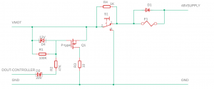
Figure 2: Electrical connection to power the motors connected to the RoboteQmotor controllers. The left portion is a current protection circuit intended to take the current generated from the motors during regeneration (when they are not controlled by the controller) and dump it so that it is not fed back into the power supply and damage it.
When an overvoltage condition is detected by the controller the digital output on the controller is activated causing the MOSFET to activate and direct the current to ground. The 48V used to power the motors is generated by an off board 48V, 20A power supply. The power goes into a relay block. The relay block is controlled by an emergency switch (S1 in Figure 2) that is powered by 12V. In the event of an emergency, the emergency switch can be activated which will cause the switches on the relays to open disconnecting power from the motors. There are two motor controllers in our exoskeleton so a second 48V line identical to the one shown in Figure 2 will be brought into the relay with a circuit protection circuit also identical to the one shown in Figure 2 on the other side. The emergency switch controls the whole relay block, so motor power to both motor controllers will be cut together when the emergency switch is activated.
September 26, 2019
Electrical wiring for the switches from Figure 1 was assembled. There are two main parts to the wiring; a 12V line to power the motor controllers and Jetson and a 48V line with a power dissipation circuit and emergency switch for the motors. Last semester a PCB was designed to distribute a 12V input. One of the 12V lines is used to power the motor controllers. Figure 3 shows the initial assembled circuit. The switch used is a single pole double through (SPDT) switch which connects the motor controller to 12V or ground. This is used because the controller must be grounded to be fully turned off.
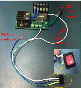
Figure 3: Motor controller power switch. One switch is shown however there will be two (one for each motor controller). The blue line goes to the motor controller power terminal, and the white line goes to ground on the controller. The green line that connects to the PCB supplies 12V to the switch.
October 10, 2019
More electrical wiring was completed. All four motor wires were extended, and the encoder wires were attached to molex connectors so that they could be connected to the motor controllers. Figure 4A shows one of the motors with wires extended and Figure 4B shows one of the encoders connected to a Molex connector.
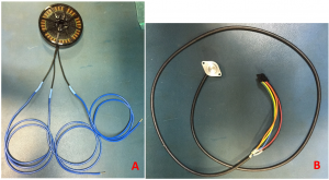
Figure 4: A is a picture of one of the motors with the wires extended. B is a picture of the motor encoder with the Molex connector connected to the end of the wires.
The switches to control the motor controllers were connected to the electrical hardware box as shown in Figure 5. The motor controllers and power distribution PCB were also mounted to the hardware box.

Figure 5: Motor controller switch wiring. This picture shows the switches ON and delivering power to the motor controllers. Each motor controller has a switch to power it on and off. The illuminated LEDs on the motor controllers signify that they are receiving power.
The Emergency Switch was wired to the system as shown in Figure 6. The emergency switch receives 12V from the PCB. It then gets connected to a relay block on the PCB. The other side of the relay block is connected to ground. There are two normally closed switches on the relay block that we are using to supply 48V to the motors. In normal conditions the emergency switch, which is normally closed, allows 12V to pass through the relay and the normally closed switches allow 48 volts to pass through to the power distribution block. When the emergency switch is activated it disconnected 12V from the relay block causing the two normally closed switches to open and stop supplying 48V to the distribution block.
Test was also performed to ensure the emergency switch worked properly.

Figure 6: Emergency switch connection. The figure shows the emergency switch connected to the 12V supply from the PCB and the reply block on the PCB. The wires connecting to the emergency switch are cutoff in this picture.
The wiring for the power dissipation circuit from the schematic in Figure 2 was completed. Figure 7 shows the completed wiring. There are two circuits, one for each motor controller.
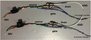
Figure 7: Two power dissipation circuits.
All the individual electrical components were connected together on the exoskeleton frame. Figure 8 shows all the wiring on the exoskeleton. All four motors were connected to their respective slots on the motor controllers. The encoders were connected to the motor connectors via Molex connectors. The power dissipation circuits were connected into the circuit. The 48V side from Figure 7 were connected to the power distribution block and then ground was connected to the ground portion of the distribution block. Dout was connected to Dout on the controller. A 12V power supply was connected to the barrel jack on the PCB to bring in 12V. The entire system was then tested to ensure all components properly received power, all switches functions appropriately, and the power dissipation circuit functioned.
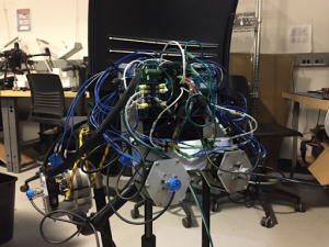
Figure 8: Completed wiring on the exoskeleton.
October 24, 2019
The wiring on the exoskeleton was cleaned up. The motor power wires were shortened and strain relief was added. Zip tie connectors were added to the frame frame so that we could zip tie the wires to the frame. This keeps the design clean and adds strain relief to the wire connections to the motor controllers. Figure 9 shows the cable management for the motor controller wires on one side. Some of the motor power wires were also disconnecting from the motor controllers. The added strain relief was used to solve this issue along with tinning the ends of the wires to provide a tighter fit in the controller terminals.
The rest of the wiring was also inspected and any loose connections were tightened.
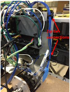
Figure 9: Cable management and strain relief for the motor wires. The image highlights the zip tie connections to hold the wires in place and add strain relief.