For the exoskeleton to accurately control the person’s movement, it needs to know certain characteristics of the person’s gait. This includes their center of mass velocity, pelvic orientations, hip angles and foot-ground contact. The sensing subsystem consists of three Inertial Measurement Units to obtain these parameters.
1 March:
In order to collect data from the IMU’s placed on the distal femur to classify foot contact, we require to integrate the IMU with a laptop to log data, as well as with force sensitive resistors placed on the foot, to get ground truth (labels). This requires us to design and build a hardware system.
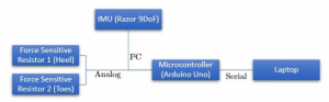
Fig 1: The block diagram for the foot contact data collection system
Soldered FSR’s with wires and integrated the outputs with the Arduino via a protoboard. Set up pins for IMU I2C communication on the board and created a 4-wire cable to connect the IMU as well.

Fig 2: FSR Setup with Arduino and IMU
4 March:
A ROS package for the Yost 3-space IMU was downloaded and installed. The package allows us to publish sensor messages to a ROS topic, thereby allowing us to visualize ROS messages in RViz.
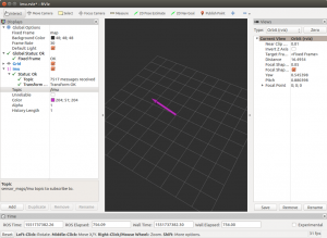
Fig 3: Screenshot of visualization in Rviz
26 March:
A ROS Package for the Razor 9DoF IMU was downloaded and installed. Custom firmware that accompanied the package was flashed onto the IMU, and the inbuilt visualizer was used to plot the orientation of the IMU in real-time.

Fig 4: Visualization of orientation of IMU in real-time
28 March:
As both IMUs independently published to the same topic, they were run in parallel with modified topic names to ensure that values did not interchange between the two IMUs. The visualizer was also modified to work with both IMUs.
7 April:
The IMUs come equipped with a powerful microprocessor that also has analog input pins. This allows us to integrate our force sensitive resistors directly to the IMU board, and simplify our block diagram by eliminating the need for an Arduino.

Fig 5: Flowchart with Arduino removed
A simple and compact voltage divider circuit was fabricated to obtain the analog values from the force sensor. A wiring diagram of this basic circuit is shown below:

Fig 6: IMU FSR setup
9 April:
The firmware of the IMU board was modified to take FSR input from the analog pins, and send this information along with the linear accelerations, angular velocities and roll, pitch and yaw values.
11 April:
On the processor side, the ROS node was modified to parse this new input and split up the information into IMU values and FSR values. This was done by generating a new message type for the FSR values and publishing them as a separate topic.
With this, the sensing subsystem is fully integrated with the processing system and can provide all the required information for performing computations.
15 April:
In order to securely mount the IMUs onto the user’s distal femurs, a 3D printed mount was designed to securely house the IMU and its voltage divider board for FSR integration. The mount attaches to the leg braces by sandwiching it between a back-plate with the help of four M3 screws.
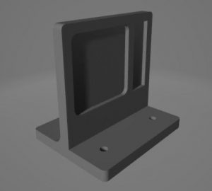
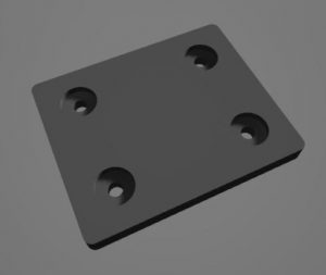
Fig 7: CAD design of IMU mount
The final hardware implementation of the sensing subsystem can be seen in the following image:
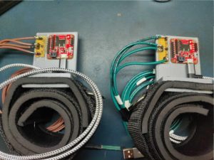
Fig 8: Integrated sensing subsystem
This completes the hardware integration of the sensing subsystem.
1 May:
Due to complications with wear-and-tear of the force sensitive resistors placed at the bottom of the user’s footwear, an alternative foot contact sensor will be explored in the upcoming semester.