The actuating subsystem receives the output positions from the processing subsystem, and actuates the hip joint to the desired positions. The actuating subsystem contains DC brushless motors, gearboxes, motor drivers, and power supply. DC brushless motors and gearboxes are chosen according to the output torque and rotation speed they can provide, as well as their prices. Motor drivers are set up with motors’ parameters and switched to position control model. Power supply is off board for the safety considerations.

Fig1: Desktop rig
- Interfaced AMC controller with a DC Brushed motor and implemented position control.
- Using the demo actuator to show that the torque is enough for lifting human’s leg.
- Final Components selection:
Motor: T-motor U8 lite KV100 DC brushless motor
Gearbox: two 1:5 Matex gearboxes to reach 1:25 gear ratio
Controller: RoboteQ sbl2360
- Current work is going through the tutorials and ROS package of the RoboteQ controller.
Update on Actuation Subsystem:
The actuation subsystem consists of the components shown in Figure 2. The power is transferred from a 48V power supply to our power distribution PCB, and then to a RoboTEQ SBL2360 motor controllers. The controllers implement position controller to drive T-motor U8 lite KV100 DC brushless motors to desired positions. The motors output torques through Matex gearboxes. For the HAA joint, we use a 1:5 gearbox to drive, while for the HFE joint, we use two 1:5 gearboxes to realize a 1:25 gear ratio.

Figure 2: Components of Actuation Subsystem
During this semester, we finished a mock demo of the actuating subsystem using a Maxon DC brushed motor, a 1:20 ratio gearbox and an AMC motor controller. We implemented a position control to the motor to drive the thigh link through a GUI. From this demo, we roughly validated that our motor can generate enough torque to lift a person’s leg. The AMC controller needs to interface with the on-board computer through EtherCAT, which is not compatible with ROS so we were unable to move forward with these controllers. We decided to switch to RoboTEQ SBL2360 DC brushless motor. Currently, we are able to power and use the controller to implement open loop control through a software GUI. We have also been able to get the available ROS package to integrate into our system.
Sep 12 2019
- Controller configuration and motor control through GUI
Using the RoboRun software, we configured the parameters of motor, feedback sensor, controller mode, and control gains. With the help of RoboTEQ technical support, we were able to do open loop control and spin the motor. In open loop control, the controller feeds constant power to the motor and actuate the motor at constant velocity with zero load. We then tried the closed loop position control with absolute encoder as feedback sensor. After naively tuning the PID gain, the motor can track the command position. We confirmed the position control by comparing the feedback signal provided by the encoder and the command position, and finding that they are the same.
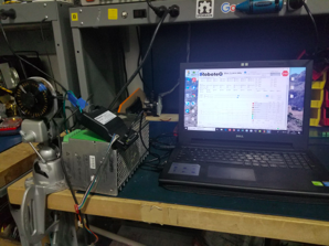
Figure 3: Motor control through the GUI
- Explore RS232 connection
We checked the user manual of the RoboTEQ controller, and followed the RS232 connection shown in Figure 2. We connected the RS232 to the laptop through a RS232 to USB convertor.

Figure 4: RS232 connection with PC
Sep 25 2019
- Controller interface with ROS through an open source package
We looked up the user manual of the RoboTEQ controller for the serial command for motor’s position control. We tested the serial command we found using the Windows GUI and validated that the command can actuate the motor to certain positions. We changed the SSI encoder configuration from “absolute” to “relative” in Windows GUI, which solved the problem that the motor was only able to spin between 0 and 360 degrees (one turn). We then were able to spin the motor to any position through the Window GUI.
We then modified an open source package for RoboTEQ controller by changing the serial commands sent to the controller as well as the structure of the input. Finally, we are able to send desired commands to the controller through ROS
- Performed position control in ROS
If the difference between the desired position and current position is big, the error input of the PID controller will be big. Sometime the controller cannot handle this big difference and actuate the motor to a “far” position, so the controller stops working. Given a desired position and the current position, if the difference is too big, we performed a linear interpolation that divided the big difference into small differences, and published commands step by step. The controller can handle the small differences and actuated the motor smoothly after the modification.
Oct 10 2019
- Integrated functions for sending serial commands to ROS
Since the open source package doesn’t work when two motors are connected to the same controller, which is what we need. We started to use a function based on C++ boost library for sending serial commands, provided by our TA Grant. We solved the environment compile issue and integrated the function into our ROS pipeline. We modified the functions to send the serial command we looked up and found useful from the controller user manual.
- Controller two motors using one motor controller
After switching to new functions for sending serial commands, we were also to control two motors using one motor controller.

Figure 5: Connection of one controller and two motors
Oct 24 2019
- Tuning the PID gains and speed limit to mitigate the “short” issue
We found that the “short” issue was caused by the big current generated at the start of the actuation. We tuned the PID gains and reduce the limit of speed and acceleration, which mitigated the “short” issue, and make the motor actuate stabler.
- Controller two motors using one motor controller
We connected the actuator with the mechanical link, tuned the parameters of the controller to make it able to actuate the leg links. We also validated that the motor can generate enough torque using a pull force sensor.
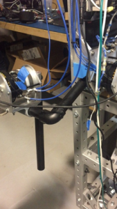
Figure 6: Connection between the actuator and leg link
Nov 7 2019
- Connected motor controller package to processing subsystem
We played a bag file containing the desired commands calculated by the processing subsystem as the input to the actuation subsystems. We kept modified parameters for the motor controller to make the whole process stable. We plotted the desired commands and motor commands together to validate that the motor can track the desired commands.
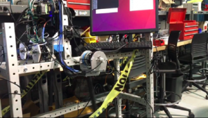
Figure 7: Actuating using the commands from processing subsystem
- Implemented free spin function
For the exoskeleton we plan to actuate the motors when the leg is in swing. However, when the leg is in stance, the person should be able to move the motors. To have this capability we need to put the motors into a mode such that they can free spin. There are three commands we can send to the motor controllers to stop the motors. There is safety stop, emergency stop, and motor stop (aka deadman switch). Safety stop and motor stop, stop the motors from moving further, however the commands cause the motors to hold their last position. Emergency stop cuts power to the motors which allows them to be rotated freely, which is the behavior we want.