Preliminary system design sketches
Performance Requirements
Mandatory
M.P.0 Will detect people in the room within 5 seconds of sensing humans within the robot’s field of view
M.P.1 Will localise the detected people in robot’s field of view up to 8m away with no occlusion and 3m away with occlusion with 0.5m radius accuracy
M.P.2 Will work in minimum 150 lux low-visibility lighting and maximum 25% partial occlusion
M.P.3 Will visualise the room geometry, obstructions, humans, and robot pose in 2D to the user for up to 10m distance from the robot with an update rate of 0.5Hz
M.P.4 Will provide a live feed from the robot to the user for use of teleoperation with 10Hz data rate
M.P.5 Will be controlled remotely by the user in teleoperation with a tactile controller for up to 40m in range with line-of-sight
M.P.6 Will be powered by self-contained energy source to run for at least 20 minutes per full-charge
M.P.7 Will record mission and critical data logs of at least the last 20 minutes
M.P.8 Autonomously detect and localize 2 people in a previously unseen room of 30m2 size within 5 minutes
Desirable
D.P.0 Should create scene representation of the explored room up to 10m horizontal distance and 1m vertical distance from the robot with an update rate of 0.5Hz
Functional Requirements
Mandatory
M.F.0 Shall detect people in the room
M.F.1 Shall localise the detected people in the room
M.F.2 Shall estimate robot pose with on-board sensors only
M.F.3 Shall visualize the room geometry, obstructions, humans, and robot pose in 2D to the user
M.F.4 Shall provide a live feed from the robot to the user for use of teleoperation
M.F.5 Shall be controlled remotely by the user in teleoperation with a joystick controller
M.F.6 Shall record mission and sensor data logs
M.F.7 Shall navigate the room autonomously without prior knowledge
M.F.8 Shall prevent itself from colliding with obstacles in the room
Desirable
D.F.0 Should visualise the room geometry, obstructions, humans, and robot pose in 3D to the user
D.F.1 Should visualize uncertainty information of detection to the user
Non-functional Requirements
Mandatory
M.N.0 Should work in low-visibility ambient lighting and in partial occlusion at room temperature
M.N.1 Should be small, light and portable enough such that the user can comfortably operate the robot alone without additional mechanical tools
M.N.2 Should be able to be operated by the user after conducting 6 hours of user training
M.N.3 Should have manuals and documentation for usage and maintenance
M.N.4 Should have an emergency stop button on both the robot and on the teleoperation device
M.N.5 Should have a watch-dog module that informs the user of any system malfunction
M.N.6 Should be visually easy to identify the robot in low-visibility environments
Desirable
D.N.0 Should be protected against airborne particulate matter and be rated at least IP5x
Functional Architecture
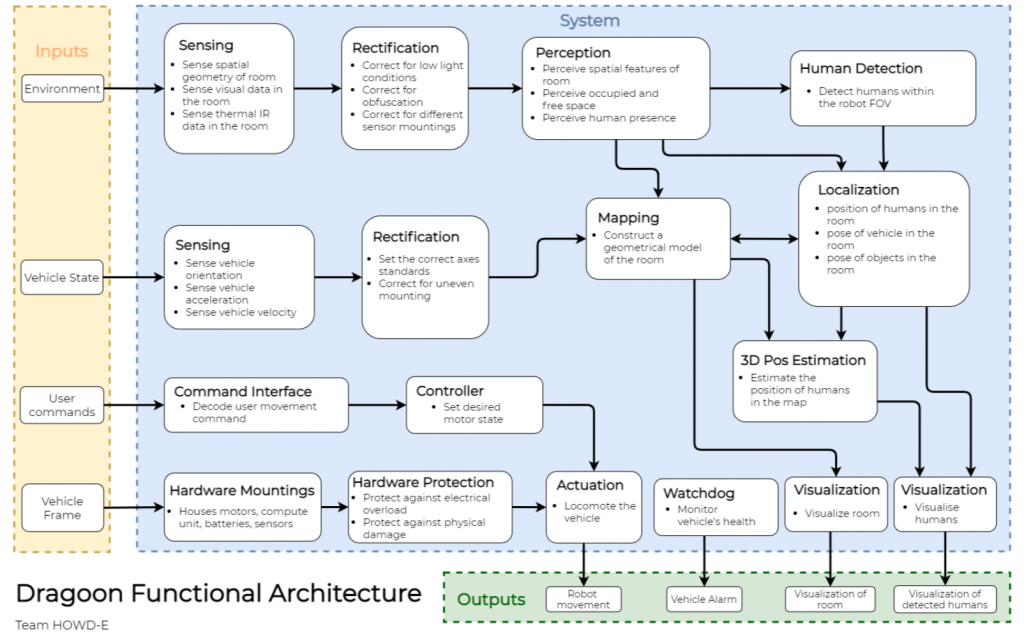
The core functionality of the system is to receive user input to locomote, perceive environmental data to extract useful features and relay back these features to the user so that they may have better situational awareness to take action in the disaster scenario.
Starting from the left input column, the robot will receive user commands specifying the desired locomotion. Combining this with an estimate of the robot’s current state, the system can then provide the necessary actuation command to reach the desired state.
While the robot is moving around inside a room, it will sense the room with several modalities. It will perceive the room’s spatial geometry and features, and any adverse lighting, dust, and fog conditions. An obfuscated environment is typical of a disaster scenario in a collapsed building.
Detection, classification and localization are principal functions of the robot and are part of the key requirements. To precisely localize these detected humans in the building, the robot pose needs to be measured accurately. Hence, while traversing the room, the robot will map and localize itself within it.
The final important piece of the system is the concise and coherent visualization of the gathered data back to the user.
This visualization need to be easy-to-understand and yet informative enough for the first responder to remotely operate the robot and to make sound judgement in the disaster scenario.
Cyberphysical Architecture
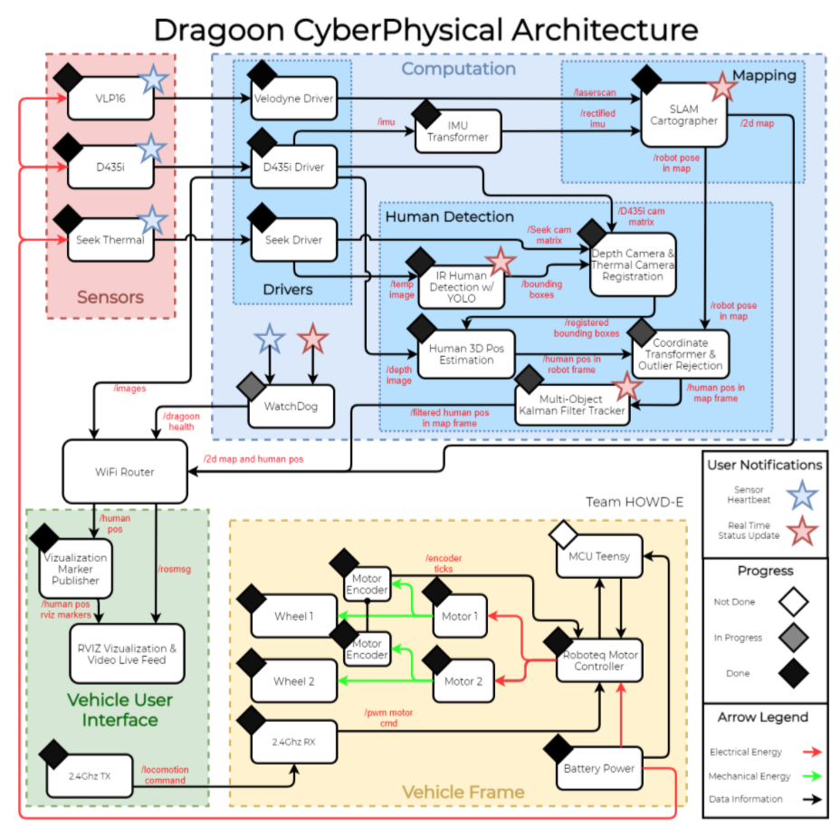
The system’s cyberphysical architecture can be broken down into four major subsystems: Sensors, Computation, Vehicle User Interface (VUI), and Vehicle Frame. The Vehicle Frame will carry the necessary hardware for sensing, compute, locomotion, and batteries. The VUI is a device for the user to send locomotion commands and to receive visualization data from the vehicle remotely. Sensors are used to gather environment data that will be passed to Computation to be processed.
The Computation subsystem can be subdivided into two main modules: Human Detection and Mapping.
For the mapping module, LiDAR laserscan data from the VLP16 and IMU/Odometry from the Intel RealSense D435i will both be utilized for SLAM. The output of this algorithm will be the robot pose with respect to a static inertial frame in the room and a 2D geometric map that can be visualized. Due to limitations of the on-board compute unit, the scene reconstruction task will be combined with the SLAM task to reduce the overall computational cost.
Human Detection is a significant part of the Computation subsystem. To reliably detect humans, a fusion of deep learning detection from RGB and thermal images will be employed. Each of the deep learning models will output 2D bounding boxes on each of its input images. The two sensor streams will need to be calibrated based on their mounting location and intrinsic camera parameters to accurately compare the two detection results. The fused 2D bounding box, depth map from stereo camera, and robot pose from SLAM will be combined to localize the human position.
Power to the sensors, compute unit, and actuator motors will be through the on-board batteries. A watchdog software module will collect sensor heartbeats and outputs from other software modules to ensure that the system is performing as intended. Otherwise, the watchdog module will alert the users of any fault or error.
System Design and Description
Full System Design
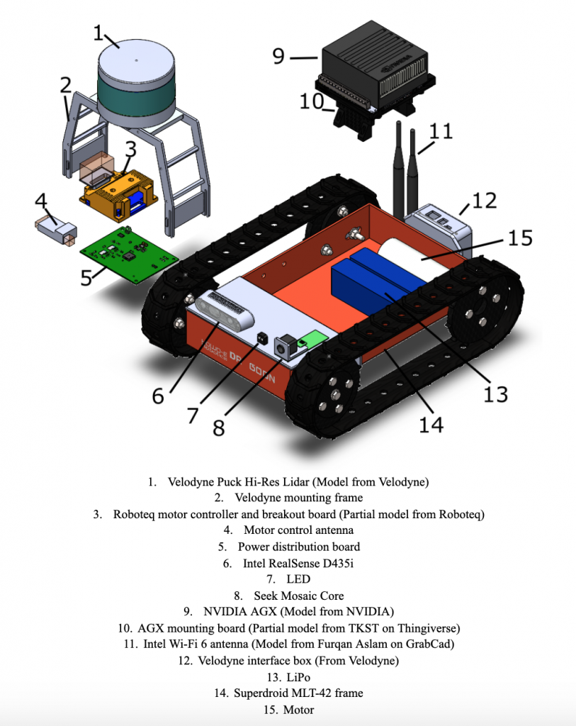
Full system design with labeled parts and sensors
The image above showcases the design of our full system. We manufactured and customized the Velodyne mounting frame as well as the power distribution board; all other parts and sensors were either purchased or obtained from the MRSD inventory.
Subsystems
1) Robot Base
For the physical base, we have decided to use the MLT-42 robot from SuperDroid robotics. It has the necessary payload requirements and fits comfortably within our budget. We are purchasing the base to include the following options when shipped out from the manufacturer:
- RoboteQ SDC2160 – 2x20A 60V Motor Controller with Encoder Input
- 2 x IG42 24VDC 078 RPM Gear Motor with Encoder
- 2 x LiPo Battery 11.1V 2200 mAh
- IG42 Gear Motor Encoder Pull-up Board
- FLYSKY FS-i6 2.4G 6CH Transmitter & Receiver
1.1 ) Power and Battery
We will be using two 3S LiPo batteries to power the system. The batteries that come from SuperDroid will give us a battery life of less than 11 minutes. While this estimate is assuming max current draw from all components, it falls far short of meeting our performance requirement M.P.6. Therefore we will be purchasing an additional two 3S 5200mAh batteries which give us a battery life of 25 minutes, which is much more suitable.
1.2) Power Distribution
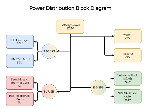
Many sensors will need to be supported on the robot base, all of which will need adequate power. Since there is a dramatic difference in the voltage levels each component needs, we will be constructing a power distribution board that will distribute power from the batteries in appropriate amounts. The board will need to include voltage protection as well as several onboard regulators.
1.3) Compute Unit
The on-board compute unit for the robot will be the Nvidia AGX Xavier Developer board. This unit has powerful embedded GPU cores and ARM-based CPU at our desired price range. It is small, portable, draws relatively low power, and is able to be powered directly with our on-board batteries. Alternatives considered include using 2 Nvidia TX2s.
1.4) MCU
A microprocessor in the STM32 series of chips from ST Microelectronics will be used in the onboard power watchdog system. STM32s have low power requirements, and also host a wide range of peripherals. Most notable among these peripherals is the USB interface, along with various other serial interfaces so that the MCU can communicate directly with the central computer.
2) Sensing
Given our performance requirement M.P.1 to function in obfuscated environments, the system has been designed to support multiple sensing modalities and leverage the strengths of each sensor.
2.1) LiDAR
Although the performance requirement M.P.3 specified that the robot only need to perceive the room geometry up to 10 metres away, we chose the Velodyne VLP-16 Puck LiDAR sensor because it is available for loan from the MRSD inventory without cost. The sensor has a maximum range of 100 metres, giving it ample margin of safety should the range be decreased due to smoke obfuscation.
2.2) Stereo Camera
The Intel RealSense D435i is the sensor of choice for this robot due to its small size, ease of use, and its 10 metres maximum depth detection range. Furthermore, the sensor leverages IR spectrum for generation of the depth image, making it more robust in environments with airborne particulate obfuscation. This sensor will additionally provide the system with RGB visual data for human detection and depth image to localize the detected humans. The camera has an on-board vision processing unit that executes the depth-from-stereo computation, relieving computation burden from the main compute unit. The Stereolabs ZED was also considered during the design process.
2.3) IR Sensor
Live humans radiate most significantly in the long-wave IR spectrum, and spectral absorption by suspended particulates including smoke, dust and pollution is lower for longer wavelengths. A preliminary analysis confirmed the feasibility of human detection with low-resolution thermal cameras. Considering the results of this analysis, in conjunction with a holistic trade-study in table, the Seek Mosaic Core with starter-kit baseboard is our final choice for IR sensor. The FLIR Lepton 3.5 was also considered during the design process.
2.4) Inertial Measurement Unit (IMU)
The chosen stereo camera (Intel RealSense D435i) has an internal IMU with 6 degrees of freedom. Hence, this removes the need to mount an external IMU, reducing cost and complexity. However, the stereo camera will most likely be mounted at a non-zero pitch angle. Careful calibration and taring of the IMU is therefore necessary to obtain accurate ground vector data necessary for the SLAM algorithm.
3) Software
The primary compute unit will be the AGX Xavier, and a small portion of computation will be done on the MCU processor. Robot Operating System (ROS) Melodic with Ubuntu 18.04 will be used as a software middleware and Operating System (OS). This is because ROS provides relevant libraries and frameworks to easily integrate different robotics software modules together through its communication protocol. All of the sensors chosen have ROS drivers available, which ensures that data can be parsed into the appropriate algorithms.
3.1) Human Detection
The human detection subsystem will primarily leverage the stereo depth camera and the IR camera. First, image calibration parameters will be determined to rectify the IR image returned by the Seek Mosaic with the depth and RGB images returned by the RealSense. RGB images will be run through the YOLOv4-tiny object detection network, returning bounding boxes and confidence levels for detected humans. IR images will first be pre-processed using radiometric data to maximize similarity with the FLIR dataset. The processed images will then be run through a YOLOv3 network that has been retrained on the FLIR dataset, similarly returning bounding boxes and confidence levels of detected humans.
The pre-determined camera calibration parameters will be used to rectify the bounding boxes from the RGB and IR detections onto the depth image. The bounding boxes will be combined using the individual confidence levels and similarity metrics (i.e. intersection over union), yielding a final single bounding box on the depth image. The location of the detected humans relative to the robot will be determined as a function of the depth pixels within the bounding boxes and known depth camera characteristics.
After humans are successfully detected and localized in the vehicle’s frame, their poses will be transformed to the map frame as defined by the SLAM algorithm. Markers to display the detected humans will be created with RViz tools and shown on RViz embedded within the reconstructed scene and map.
3.2) SLAM & Scene Reconstruction
SLAM is a critical component of the system as it will map out the geometry of the room for scene reconstruction and provide the robot pose in the map frame for a global localization of detected humans in a fixed inertial reference frame. The Cartographer package is the ideal candidate for this task. It is a LiDAR-based SLAM that is able to accurately map an environment with robust loop closures. Initial testing of the algorithm has shown that is able to provide high fidelity and detailed maps, so it can be used to perform both robot pose estimation and scene reconstruction.
3.3) Motion and Control
Even though the robot will be controlled through teleoperation, data on the vehicle’s odometry is crucial to aid the rest of the system. Given that the robot is driven with tracks, the skid steer vehicle model is suitable to model the kinematics of the system. The equations of motion are as follow:
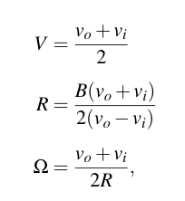
V is longitudinal velocity, R is radius of curvature, B is the end-to-end vehicle width, vo, vi are the outer and inner velocities respectively, and Ω is the vehicle’s heading velocity.
3.4) Defogging
Because our system is required to work in obfuscated environments as per M.P.1 and M.N.0, it is imperative that we be able to defog our sensors. The image defogging method we will be using for our RGB camera is the Dark Channel Prior method. This algorithm exploits the observation that the majority of local regions include some pixels that are characterized by a low value in at least one color channel. This helps estimate the transmission map of the hazy images. We are choosing this method because it is simple, accessible, and fast. Alternative image defogging algorithm explored include non-local image dehazing and image dehazing using boundary constraint and contextual regularization.
There is considerably less research in the field of LiDAR defogging than in that of image defogging. As such, more hands-on testing will be required to resolve this issue. Our current research shows that fog and haze will degrade the range of the HDL-64 LiDAR (a LiDAR very similar in range and functionality to the Velodyne Puck we will be using) from 100m to around 25m; assuming a similar performance from our Velodyne Puck, 25m should be sufficient for our purposes given that we are working in purely indoor environments. Should performance degrade more than expected, several methods can be used to correct the LiDAR data. Rudimentary methods done by other researchers include tuning the initial parameters of the sensor (i.e. adding power) and setting a false alarm or noise threshold. More complex methods include using convolutional neural networks to distinguish between data bounced back from fog versus data bounced back from objects. However, none of these methods have been tested and proven on a large scale and we are currently working with researchers at Draper to develop a more robust solution.
4) Vehicle UI
The main visualization tool for the user will be RViz, an open-source visualizer that is tightly integrated with ROS. We are planning to compose the complete scene in RViz and display it on a portable laptop. The data will be transmitted over Wi-Fi.
4.1) Teleoperation and Live Feed
We will be controlling the robot with a radio controller that comes with the robot base from SuperDroid. We are expecting for this to work out of the box since the manufacturer claims it does. In order to mitigate risk as we develop the teleoperation system we will perform extensive testing with the RC and receiver before putting our sensors on it. The live feed will be broadcast through Wi-Fi to the operator’s computer, where it will be displayed for the user to see in RViz.
A potential stretch goal in this area is to control the robot through Wi-Fi from the visualization on the laptop, resembling a computer game. However, we are not including this in our current scope due to the amount of effort required.