Actuated Manipulation Subsystem
The actuated manipulation subsystem has two high-level tasks: to move the end effector to an obtainable 3D goal pose and to maintain a 3D goal position relative to the global coordinate frame.
Design Choices:
- We performed a trade study to determine the preferred motion planning algorithm. The options included two variants of Rapidly-exploring Random Trees (RRT) and Probabilistic Roadmaps (PRM). The RRT-Connect algorithm was chosen for its slightly faster reported computational runtime as well as its ability to be processed as needed, as opposed to PRM* . RRT* was not chosen because its ability to optimize trajectory paths over time was not preferred in the use case where the user is preferring quick runtimes of the robot arm rather than smooth end effector trajectories. PRM* was not chosen because it needs to sample the environment prior to building a path and its un-optimized runtime when in a non-static environment.
- To reach to more 3D goal positions in our defined task space and achieve more versatility for our stabilization requirements, we redesigned the manipulator arm from a 3 degree-of-freedom to a 4 degree-of-freedom manipulator arm. The fourth motor serves as a laterally rotating shoulder joint, allowing the arm to reach more of the task space towards the left and right side of the user wearing the COBORG. In addition, the total length of the arm became longer and is positioned lowered on the backpack frame in order to reach more goal positions closer to the horizontal orientation (i.e. pushing out positions) without sacrificing any capability along the vertical orientation (i.e. pushing up positions).
- To perform motion compensation and stabilization, we implemented a Resolved Rate controller. The controller is a closed-loop cartesian position controller based on the cartesian error between the current position of the end effector and the updated 3D goal position from the vision subsystem. From the error, desired changes in the joint configuration is computed using the Jacobian matrix relative to the end effector frame. Using a weighting matrix, different joint actuations can be prioritized in order to facilitate consistent and stable performance from the controller.
Implementation was done by utilizing the following ROS packages: MoveIt and HEBI C++ ROS API. Motion planning is performed considering both static and dynamics obstacles.
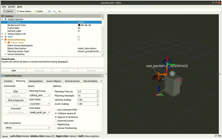
Figure 1A. Actuated Manipulation System Demo
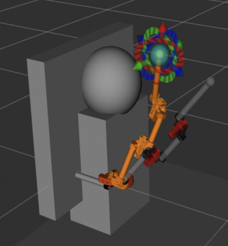
Figure 1B. URDF for the Upgraded Arm with 4 Motors
Vision Subsystem
Technical Lead: Yuqing Qin
Secondary: Feng Xiang
The vision system aims to localize the target part location and send the goal position to the motion planning system. To achieve this goal, the vision system utilizes the YOLO v3 hand detection algorithm along with the point cloud information to detect the target part position. Also, the vision system outputs the surface normal of the target part, which will be used in the later integration and stabilization task.
Design Choices:
- We performed a trade study to determine the ideal method of part detection. The options compared include detecting the user’s hands (Hand Detection) and calculating a center point, using a laser pointer (Laser Pointer Detection) to identify a location on the part, direct identification and detection of the part (Part Detection), and adding a detectable aruco marker(Aruco Marker Detection) to every part. The hand detection method was chosen as the best option because it is a reliable, hands-free method that would require minimal part manipulation. The laser pointer method was not chosen because the user would have to hold the laser, defeating the purpose of our “hands-free” device. The part detection method was not chosen because the part will be invariably occluded, which is a major problem for computer vision algorithms. Additionally, every type of part would have to be trained into the computer, which would have to reliably distinguish between them. The aruco marker method was not selected because it would require the company to add aruco markers to all of their parts that they intend to use with this device, defeating our value proposition of lowering annual costs.
- To deploy the vision system on multiple camera streams, we have to rethink our trade study. Running multiple vision systems on Jetson gives power limitations. We started from YOLOv3, which has poor inference time on two cameras. We are currently working on YOLO v4 tiny and TensorRT to speed up the whole process.
The vision subsystem decided to use the hand position (currently retrieved from YOLO v3) and further utilize it to infer the object location. The object location will then be used in the motion planning and actuated manipulation subsystem.
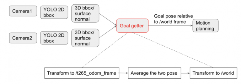
Figure 2A. The Vision System Pipeline
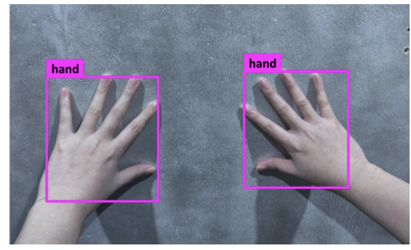
Figure 2B. Hand detection demo

Figure 2C. 3D hand bounding box
Voice Subsystem
Technical Lead: Gerald D’Ascoli
The voice subsystem will serve to interpret the verbal commands given by the user and translate them into commands recognized by the COBORG system. Currently, the voice system could recognize commands like “Hey Coborg, go here”, “Hey Coborg, come back”, “Hey Coborg, stop”, and “stop stop stop” for emergency stop.
Design Choices:
- We performed a trade study to determine the ideal voice recognition software. The options compared include using Google’s API (Speech_Recog_UC ) , using the CMU-developed PocketSphinx , and building software from scratch. The PocketSphinx software was chosen as the best option because it is a fairly accurate package that is relatively easy to implement, and doesn’t require a connection to the internet. Speech_Recog_UC was not chosen because, while it’s highly accurate, and the easiest to implement, we cannot guarantee a stable Wi-Fi connection in a manufacturing environment. The build from scratch method was not selected because it would take far too much time and we could not guarantee it would have sufficient accuracy. It should be noted that, in the event of unforeseen time constraints, using Speech Recog_UC would be entirely acceptable, but PocketSphinx is preferable.
This is currently accomplished with speech-to-text for keyword recognition and translated through CMU PocketSphinx.
Figure 3. Voice System Demo
Mechanical Hardware Design
Technical Lead: Husam Wadi
The COBORG backpack is built on the foundation of a sturdy, lightweight hiking backpack frame. The ergonomic shape and cushioned straps allow the users to comfortably operate for hours at a time. The electrical systems are securely attached to the center of the backpack and 80/20 robot units provide an attachment between the frame and actuators. Strong, lightweight aluminum tubes connect the COBORG’s motors, offering superior strength while reducing user load.
Design Choices:
- We performed a system-level trade study, to determine the best mechanical framework for our task. The other options include a motor-linkage arm, a robotic “snake” arm, a sliding gantry arm, and a tendon-actuated arm. The most important criteria from our trade study were the Operational Cost, Ease of Operation, Simplicity, Range, and Mechanical Advantage. The criteria for this trade study were derived from the performance and non-functional requirements. The motor-linkage arm was chosen as the best option because it provided many advantages over the other robotic options and at a much lower annual operational cost than the human alternative.
- We are currently working on upgrading the hardware setup from the 3 motors version to 4 motors to further expand our task space. By doing simulation through MoveIt, we tested with 4 motors and 5 motors with different configurations (i.e. linkage length). By checking their task space coverage, we decided to go with the ‘4 motors’ plan since it could cover 95% of our predefined task space listed in our requirement without adding too much complexity and weight to the arm.
- We are also considering the upgrades on the sensor system. Since our current sensor system (one D435i + one T265) cannot fulfill the requirements of the task space, we considered other alternatives, including ‘two D435i stacked vertically’, ‘two D435i on each side of the robot’, ‘one D435i with motor’, and ‘one D435i put on the head’. Since our system has a higher priority on vertical FOV, we decided to go with the ‘two D435i stacked vertically’ plan.
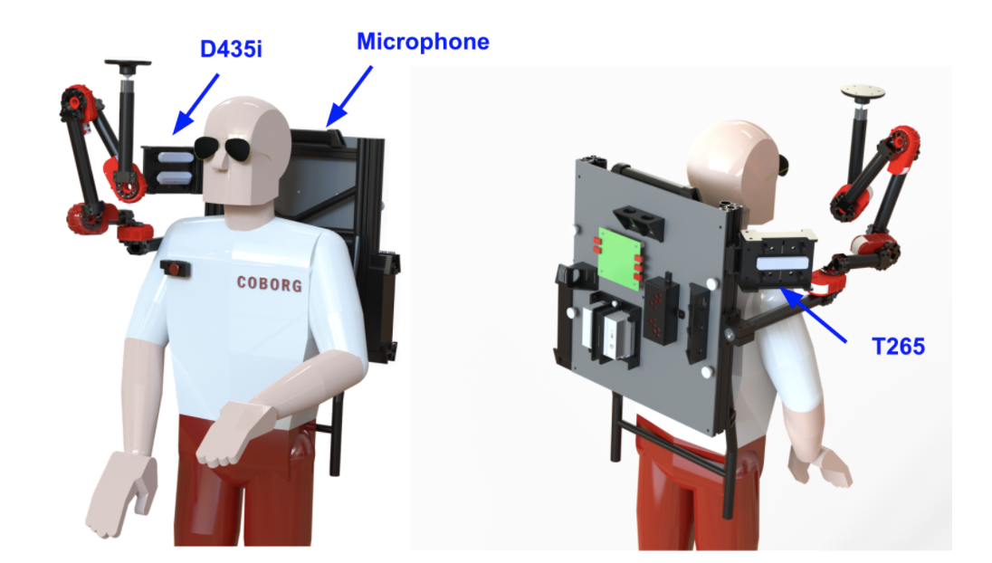
Figure 4A. CAD for the upgraded robot
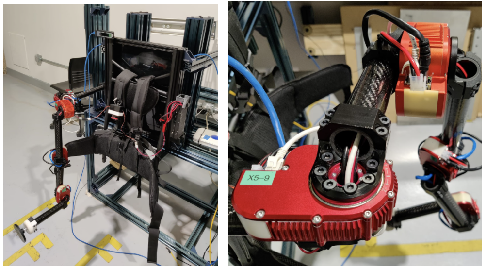
Figure 4B. The upgraded hardware framework and motors
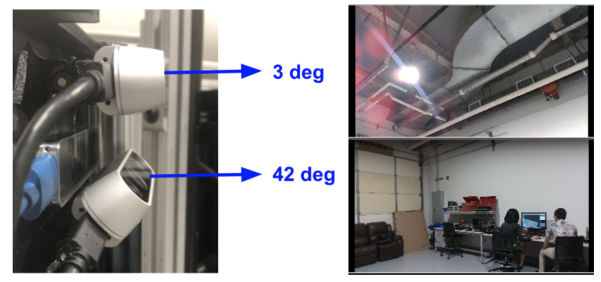
Figure 4C. Upgraded sensor set and the extended view
Electrical Design
Technical Lead: Gerald D’Ascoli
The electrical subsystem will comprise of all PCBS and control signal wire routing as well as the power electronics for tethered, untethered, and charging operational modes of the COBORG.
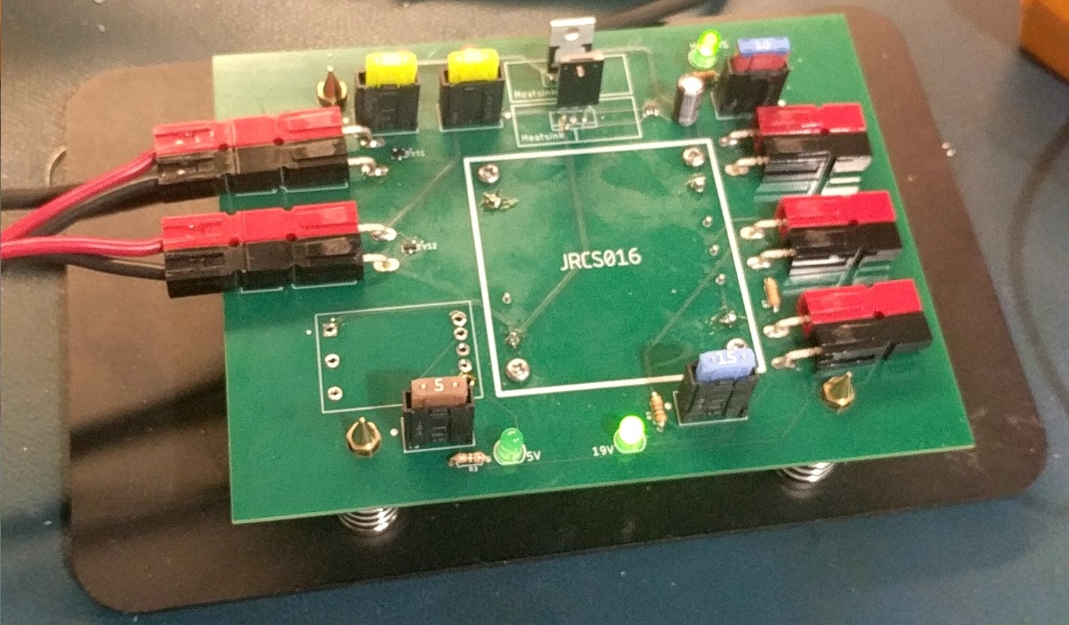
Figure 5. PCB demo
Software Framework
Technical Lead: Jonathan Lord-Fonda
ROS Melodic serves as the software framework of this robot. Installed onto a portable Ubuntu 18.04 workstation, the framework well integrated with all components of the robot, whether the API’s are built with Python or C++.

Figure 6. Software Framework Design