Vision Subsystem:
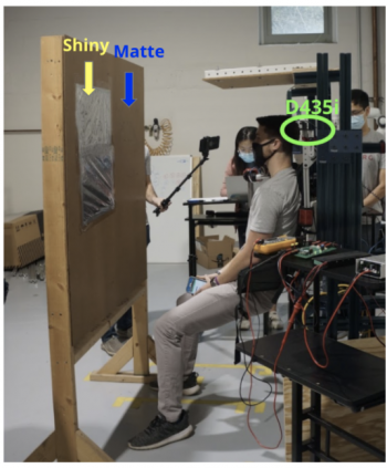
The vision subsystem performance is evaluated in the above experiment setup. To easily measure the ground truth and the prediction value, we fixed the COBORG on a frame. The depth camera (D435i) is on the left shoulder pointing straight to the board. To validate the consistency of the performance, 10 predefined positions on two different part textures (i.e. shiny, matte) are prepared on the board to test. Figure 1 shows the experiment setting for vision system validation testing. These 10 predefined positions cover different moving directions of hands and different distances between two hands. Table 1 gives the summary of the SVD results on vision system.
Voice Subsystem
Figure 2. Professor Dolan’s Voice Recognition Testing
The results in Table 1 are from an isolated validation test with the microphone mounted on the COBORG using Gerald’s voice for the test. 150 voice commands were tested including the command to go to the user’s goal target, the command to compact to the arm, and the emergency stop command. A successful output was defined as an accurate recognition of the intended command in at most 2 tries. This criterion was defined based on irritation, if a command takes more than 2 tries to recognize then it irritates the user and defeats the purpose of convenience of voice control. After each trial of three commands, a randomly generated sentence of at least 20 words was read to test if the voice system would detect the keyword “COBORG” trigger in random speech. The goal of this test is to validate the 60% recognition accuracy dictated by requirement P.M.4.1.
Actuated Manipulation Subsystem:
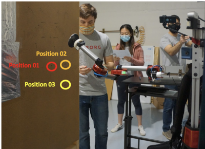
Before SVD, the actuated manipulation subsystem was tested on 3 pre-measured positions on a vertical board directly in front of the robot arm distanced about 90 centimeters away from the robot frame. Each of the 3 pre-measured positions was tested a total of 6 times. The robot arm was commanded to go to these goal positions from the compact/home position. The robot arm was allowed to pass through two intermediate positions between the compact/home positions and the goal position. When the robot arm reached the goal position, a tape measure was used to measure the error distance between the ground truth pre-measured point and the landed position of the end effector on the board. The end effector has to be firmly pressed onto the board. The robot arm was when commanded to go back to the compact/home positions. The robot arm passed through the same two intermediate positions before reaching the compact/home position. Once the robot arm reached the position, a measurement was taken with a tape measure between the base motor and the end effector tip of the robot arm.
The setup image above shows the 3 pre-measured goal positions that were tested on the COBORG during SVD. Position 02 was set orthogonally to the right from Position 01 by 15 centimeters. Position 03 was set orthogonally downward from Position 02 by 15 centimeters.
Results Summary:
| Subsystem | Metrics | Success Criteria | Performance on SVD |
| Perception: Vision | Euclidean distance error, Surface normal angle error, Execution time | Distance error < 6 in (~15cm) Angle error < 45 deg Execution time < 5s | Avg. distance error =3.74cm Avg. angle error = 4.17deg Avg. execution time = 1.3s (Avg. on 10 testings) |
| Perception: Voice | Binary Recognition Accuracy/Command | 60% Recognition Accuracy | 100% recognition accuracy |
| Actuated Manipulation | Euclidean distance error Euclidean distance error, base-to-end | Distance error < 6 in (~15cm) Compact distance < 20 in (50.8 cm) | Avg. distance error = 1.46cm Avg. compact distance = 34.5 cm |
| Non-functional | Digital bathroom scale | Weight < 40 lbs | Weight ~= 17.5 lbs |