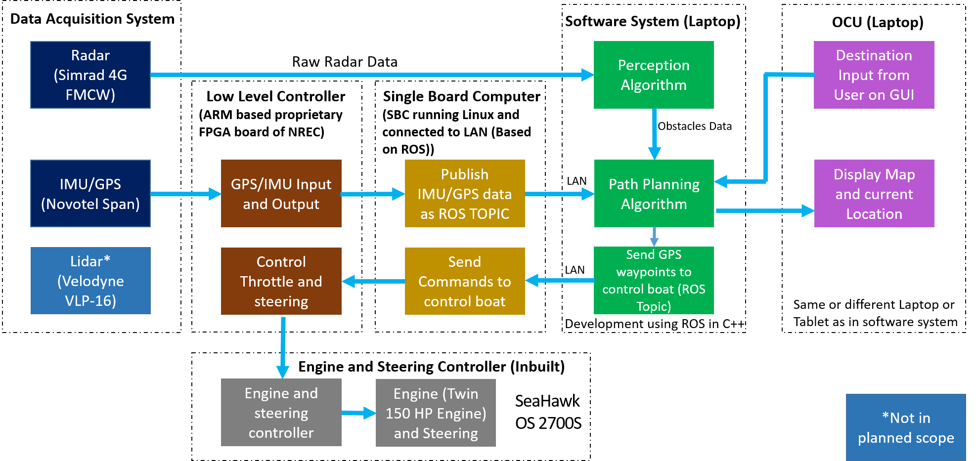
As shown in Figure 1, the Cyber-Physical architecture is divided into 4 systems namely –
- Data Acquisition System
- Software System (Laptop)
- OCU(Laptop)
- Engine and Steering Controller (Inbuilt)
1. Data Acquisition System
As the name suggests, The primary function of the data acquisition is to acquire data from the various sensors that are installed on the boat. Currently, there are 3 sensors that are installed on the boat –
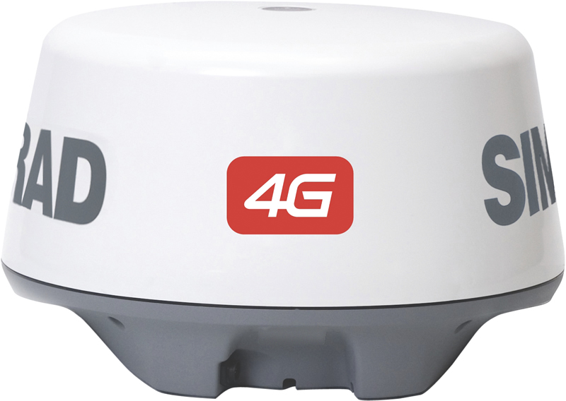
- RADAR SimRad 4G FMCW Radar
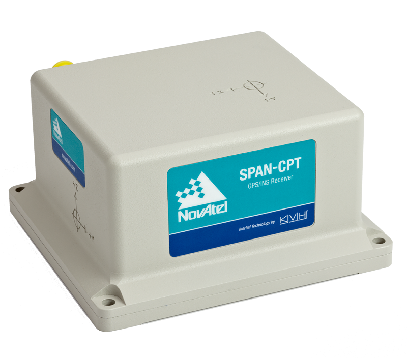
- IMU Novatel SPAN
- LIDAR Velodyne VLP-16
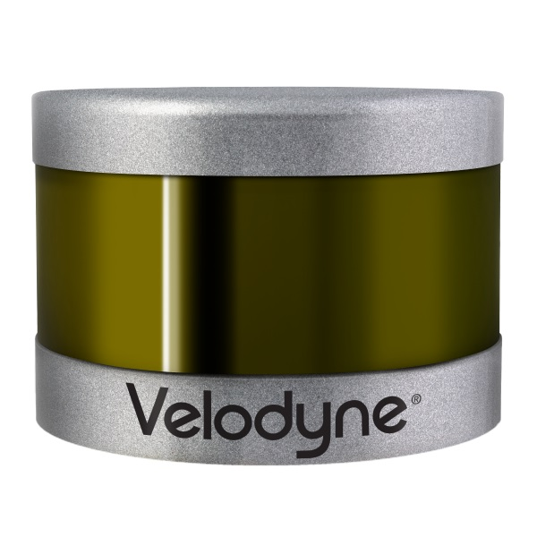
RADAR data will be used to detect obstacles like other ships, bridges and shores. The IMU which is GPS enabled will be used to acquire GPS data, velocity, and orientation from the IMU. As of now, as per the requirements of the sponsor we are not using the LIDAR sensor but we might use it if we do not get the desired results by using only the RADAR.
Once we have the data from the sensors(RADAR and IMU), the next step is to use this data to find the GPS location of the boat using IMU data, detect obstacles from the RADAR data. Once, we have the location of the boat and the positions of the obstacles are in the environment, we need to plan how the boat navigates to the navigation. All these jobs are done by the software system. Since this is a software intensive project, this system is the heart of the project.
2. Software System (Laptop)
In the software system, we have 2 subsystems –
- Perception
- Path Planning
The perception algorithm uses the RADAR data to detect obstacles like boats, shore, bridges etc and feeds this data to the path planning algorithm. The path planning uses this higher level data along with the IMU data to plan the path. As of now, we have not decided which frameworks and algorithms we’ll be using in the software system.
3. OCU (Laptop)
Operator Controller Unit (OCU) is a user interface device interacting with the controller of autonomous water taxi. OCU provides the visual information and takes commands. OCU shows map with location and
trajectory of the water taxi and other boats sailing around it. An operator can input destination information which corresponds to existing ports.
4. Engine and Steering Controller (Inbuilt)
The last system is the Engine and Steering Controller. Most of the low level control has been already done by engineers at NREC. We only need to send high level commands to the engine controller to change the speed and direction of the boat.