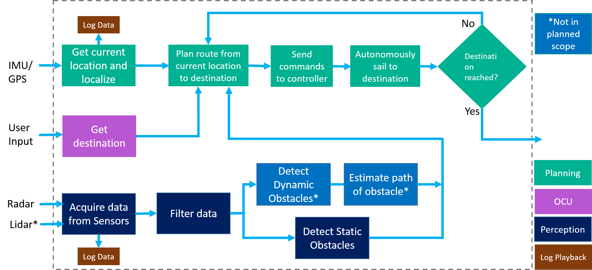
Figure 1 describes the functional architecture of the Autonomous Water Taxi. The functional architecture can be viewed as the building blocks of elements spanning across perception, planning, OCU and Log Playback. The desired output of the system is that the autonomous boat reaches the final destination by avoiding obstacles. The input of the system is user input, which specifies the way points and destination, and the data acquired by sensors, which includes IMU input that gives data of current position(GPS coordinates, heading), and Radar and Lidar which detect the objects.
First part of the functional architecture is obstacle detection based on Radar and Lidar. The system acquires data from Radar and Lidar sensor, which we can log and play back that data for further analysis purposes. Since it will consist of a lot of noise in the data got from the sensors, especially for the radar, the next step will be filtering the data to get the useful information that indicates the size and location of the obstacles. For the obstacles, we need to divide the obstacles into two categories, static obstacles and dynamic obstacles and then design different strategies for them, because for dynamic obstacles we need to estimate path of it and then decide to follow its path or just avoid it. And we will get obstacle avoidance algorithm for this part finally.
The second part of the system is Log Playback. Log Playback allows us to log the data from the sensors(RADAR, IMU) and then analyze and implement algorithms based on the data. It also provides required information for the OCU module, and finally shows in the user interface.
The third part is Operator Control Unit (OCU), which allows user to specify the geometry location, usually the longitude and latitude, of waypoints and destination. The idea of the water taxi is that we implement an autonomous driving boat and users are able to use the mobile app to order a taxi service, and the water taxi will pick up passengers at each point and plan a path.
The final part is path planning which gathers data from IMU sensor to get the current position and location of the autonomous boat. The IMU sensor has an embedded high-accuracy GPS and digital compass to get an accurate location and gives to the path planning module as the input. The path planning function gets the input of current location, destination and the information of the dynamic and static obstacles. Then it plans a path for the autonomous boat to reach each way point without hitting any obstacles and sends accordingly give commands to the low-level controller. Then the following function will estimate the current location and check if the autonomous boat reaches each way point and finally arrives the final destination successfully. If the autonomous boat has not reached the destination, then it will go back to the path planning function and design a new strategy for path planning with updated input from sensors.