For a overall flow of our Collision Avoidance System works, refer our functional architecture.
Following are the major subsystems of Delta Autonomy’s Collision Avoidance System. This product is currently in development and the status bar highlights each subsystem’s progress.
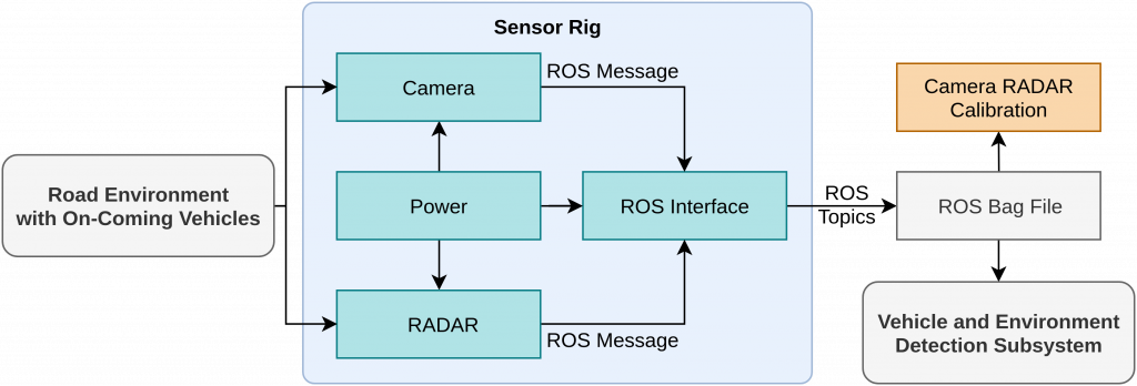
Data Acquisition Subsystem
The sensor rig is the part of the Data Acquisition Subsystem.
![]()
There are three major sources for data acquisition, including:
1. Sensor Rig – This is the source of real-life data. A sensor rig will be designed and fabricated on which the camera and RADAR sensors will be mounted at positions similar to an actual truck. These are some of the few scenarios through which data will be generated.
Scenario 1: We will place the sensor rig unit on the side of the road and acquire data.
Scenario 2: We will place the sensor rig unit in a deserted place near Pittsburgh and acquire data by driving a car towards the sensor rig to create crash like scenarios.
2. Labeled Datasets – We will also use existing labeled datasets such as KITTI and Cityscape to train our vision based models for object detection and road segmentation. These dataset sources (real and synthetic) have their own pros and cons. Real data will have
accurate sensor noises which is important to generalize our perception algorithms. The downside is that it is difficult and unsafe to acquire real-life data. With the help of simulators, we can generate all the relevant data easily but with the data will lack realistic sensor noises. A combination of both these types of data will be used to develop and train our algorithms.
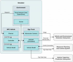
Simulator Subsystem
The sensors will be mounted on the simulator vehicle and various crash and crash-like (near miss) scenarios will be created. The environment conditions will be according to our use case i.e. straight two-lane highway roads with clear skies and day light conditions.
![]()
3. Truck model
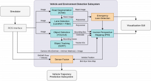
Vehicle and Environment Detection Subsystem
![]()
The main goal of the perception subsystem is to detect oncoming vehicles and estimate their position and velocity. In order to estimate their position on the roads with respect to our truck, we need to detect the road layout and lane markings, which is also required for planning evasive maneuvers. We will primarily be using vision and range data for this. For lane detection we will use classical feature based methods using libraries such as OpenCV, which can work in real-time. For road segmentation we will use deep learning based models such as DeepLab v3 or Masked RCNN to estimate the road layout and area. Road and lane detection is used to estimate the lateral position of the on-coming vehicles in the scene. To detect the vehicles using visual data, we plan to use single-shot object detection models such as YOLOv3 and Single Shot Multibox Detector (SSD) . We can achieve the desired accuracies with real-time inferences as per our performance requirements with these models. These pre-trained models will be fine-tuned using transfer learning on labeled datasets such as KITTI and Cityscapes along with data that we will be generating from our simulators and sensor rig. Recovering the 3D velocity of the vehicles solely based on vision is very challenging and in-accurate, especially for long range detection. We complement the detection with the help of a combination of short range and long range RADAR. We can estimate the position using the radio wave time-of-flight and velocity by analysing the transmitted and the reflected radio wave frequency (Doppler effect). The RADAR data in the form of polar coordinates can be accessed via the CAN bus by interfacing it with NVIDIA Jetson TX2. The data is then preprocessed for noise and transformed to Cartesian coordinates. Camera and RADAR sensors have complementary capabilities. RADAR is excellent for determining speed of oncoming vehicles and operation in adverse weather and lighting conditions, whereas camera provides rich visual features required for object classification. Now we improve the position and velocity estimates from both the RADAR and camera using sensor fusion to improve the reliability. We plan to use off-the-shelf fusion algorithms such as Extended Kalman Filter, Unscented Kalman Filter or Particle filters based techniques such as Monte Carlo Integration. The final step is to track the vehicles over time using techniques such as Kalman Tracking or Lucas-Kanade based Optic Flow methods.
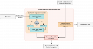
Vehicle Trajectory Prediction Subsystem
![]()
This subsystem is critical to the process of deciding the dynamical response to be generated by the ego vehicle. Here, the possible trajectories of all detected vehicles is predicted and the ego-vehicle trajectory is estimated. This is a regression problem because we not only have to predict where a vehicle might go based on its current state (a classification problem), but also predict its position in the near future. Long Short-Term Memory (LSTM) neural networks, which are a particular implementation of recurrent neural networks will be employed to solve the trajectory prediction problem. LSTMs keep memory of previous inputs and as such are considered extremely efficient for time series prediction. The network will be trained on data gathered from the mechanical sensor rig, data generated from the simulation platform, as well as from the Datasets available online. We will define every detected vehicle as the target vehicle and for every target vehicle we will consider various observable features such local lateral position, local longitudinal position, speed of vehicle and type of vehicle. These features will be provided by the output from the Vehicle and Environment Detection Subsystem. For any given vehicle for which the trajectory is to be predicted, based on a new input state, its previous state and previous output, a new output state is produced, thus providing a trajectory. A downside to regression problems is that they only output a single point (a single predicted trajectory). To overcome this, methods such as Monte Carlo sampling may be used.
Maneuver Planning and Controls Subsystem
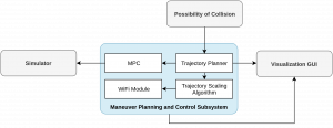
![]()
The planning and controls subsystem is responsible for generating the best possible evasive maneuver in the case of an impending collision. It will receive pose data from the simulator and the information about ego-vehicle’s and on-coming vehicle’s future trajectories from the occupancy map. The trajectory planner will plan evasive trajectories which will try to mitigate the effects of the crash by reducing the speed of the truck and manoeuvring it into the emergency lane on the side of the road. At each timestep, the trajectory will be recalculated while incorporating the information about the changes in the environment. The trajectory is sent to the Model Predictive Controller which converts the velocity and yaw rate information from the trajectory to steering angle and throttle/braking commands. MPC will have information about the dynamic model of the car which makes sure that the control commands are within the reachability set of the actuators. The truck in the simulator receives these command and executes recovery actions to mitigate the effects of a collision.
RC Car Subsystem and Localization Subsystem
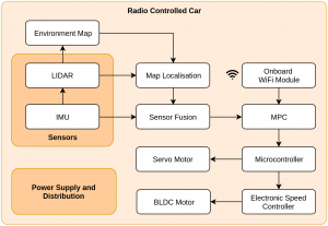
![]()
RC car will be used for physically validating the planning and controls subsystem. The RC car platform will include a BLDC motor, ESC, servo motor, battery, chassis, drive train, wheels, and suspension. The RC car will have an on-board computing system (NVIDIA Jetson TX2) which will be used to carry out all the processing. We plan to use existing packages for navigation and localization present in Robot Operating System (ROS). The WiFi module of the computing system will be used to receive scaled trajectories from the master computational platform in the form of ROS messages. These trajectories will have velocity and yaw rate information and using Model Predictive Control, the data is converted into steering and motor throttle commands. The controller will be be updated with the current state of the vehicle from the localization module, consisting of LiDAR and IMU sensors mounted on the vehicle. The control commands will be sent to the microcontroller which will further send it to the Electronic Speed Controller (ESC) and the servomotor. The ESC is responsible for controlling the BLDC motors which power the wheels of the RC Car. The steering servo motor is connected to the knuckles mounted on each of the front wheels through a six-bar steering mechanism A mapping from the servo motor angles to the steering wheel angles will allow the microcontroller to send the right commands to the servomotor.
In order for the RC car to execute the maneuver, it is important that it knows where it is in its environment and localize itself. The RC car may get information from two sources i.e idiothetic and allothetic sources. Idiothetic source includes odometry information which means estimating the absolute position by using dead reckoning methods but this is prone to cumulative error. Com- bining this with allothetic sources of information such as a LiDAR reduces these error values. LiDAR will help the RC car get important information about the features in its environment and an IMU will help in determining its state such as its heading over time. After filtering these sensors data from noise, mapping is performed by using Simultaneous Localization and Mapping (SLAM) techniques. Finally, the data from the sensors is fused and the pose and other state variables of the RC car are estimated by matching features of interest onto the map created using SLAM. Adaptive Monte Carlo Localization (AMCL), a type of particle filter localization will be implemented.
Data Visualization Subsystem
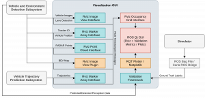
![]()
The data visualization subsystem is common to all the above mentioned subsystems and its primary objective is to help visualize the environment’s map. We plan to implement this with the help of ROS Visualizer (RViz) and other Python libraries. This GUI based module will display a 2D map of the estimated position of all the other vehicles around the ego vehicle, along with their velocity and estimated trajectories (or probabilistic regions). In case of detected collision, the planned maneuver can also be visualized. Apart from these features, this module can be used to display running average accuracies of vehicle detection and trajectory prediction models, given the ground truth data form the simulator.
Alert Subsystem
The alert subsystem is a part of the Collision Avoidance System which will generate an acous- tic notification/alert to alert the truck driver, in the case of collision detected and the horn in the simulator / buzzer on RC car will be activated to alert all the other drivers on the road.