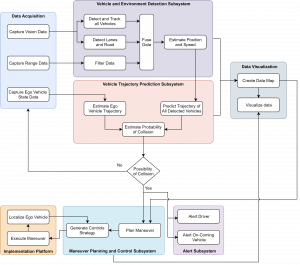
FUNCTIONAL ARCHITECTURE
The Collision Avoidance System (CAS), broadly speaking, performs three things in totality -it Detects, Analyses and then Responds. These tasks have been segmented into seven subsystems which were derived based on the requirements of our sponsors and stakeholders as well as the team’s internal requirements and objectives. The Data Acquisition Subsystem captures various types of data such as vision data, range data and ego-vehicle (self-vehicle) state data. The vision and range data is then subsequently fed it into the Vehicle and Environment Detection Subsystem. Using the vision data, this subsystem detects and tracks all surrounding vehicles, as well as, detects lanes and roads. It then provides reasonable but limited estimates of positions of all the vehicles. The range data fed into this subsystem is filtered for noise and then fused with the output of the vision data. This fused data not only has better estimates for positions but now is coupled with velocity estimates as well.
The Vehicle Trajectory and Prediction Subsystem performs three tasks in essence. Firstly, it uses the ego vehiclestatedataobtainedfromtheDataAcquisitionSubsystemtoestimatethetrajectory of the ego-vehicle. Secondly, it uses the output from the Vehicle and Environment Detection Subsystem to predicts all possible trajectories of all the detected vehicles. Finally, it calculates probabilities of collision between ego-vehicle and all detected vehicles. The output from the Vehicle and Environment Detection Subsystem and the Vehicle Trajectory and Prediction Subsystem is then used to create a data map to visualize the data which is realized by another subsystem called the Data Visualization Subsystem. The probabilities calculated in the Vehicle Trajectory Prediction Subsystem is compared with a threshold value. If the probability is low, the system loops back and continues do all of the same. If the probability is higher than some threshold, two more subsystems get activated simultaneously. The Alert Subsystem warns the ego-vehicle driver and the oncoming driver. In parallel, the data map created in the Data Visualization Subsystem supplies information to the Maneuver Planning and Control Subsystem which plans an evasive maneuver and feeds this data back into the Data Visualization Subsystem, in a loop. The Implementation Platform Subsystem consists of a dynamical system which takes in a desired trajectory to be followed in the form of a control strategy as input and uses this input to evolve its state over time. This subsystem takes its input from the Maneuver Planning and Control Subsystem which feeds in a closed loop control strategy. The closed loop control strategy is achieved with the help of a localization module on board the implementation platform. Finally, the Implementation Platform executes desired the evasive maneuver.
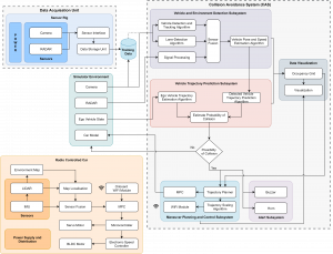
CYBER-PHYSICAL ARCHITECTURE
The cyber-physical architecture of our system is inspired from the functional architecture with nearly the same subsystems. These subsystems can be classified into three major types: Hardware based subsystems, Software based subsystems or Simulation subsystem. The Hardware based subsystem consist of the Data Acquisition Unit and the RC Car. The Data Acquisition Unit consists of Sensor Rig which is used to collect data in the real world using automotive grade Camera and RADAR obtained from the sponsors. These sensors have to be connected to the data storage unit using a sensor interfacing unit.
Since it is very difficult to find or collect real world crash dataset, we model the environment and the vehicles in a Simulator and collect crash dataset for training our models. Simulator has an ego-vehicle (truck) model with accurate dynamics which allows proper testing of our response algorithms. The truck has Camera and RADAR models mounted on it at positions similar to the actual vehicle. The performance achieved on the real world dataset (obtained from the sensor rig) is compared with the performance on a test set obtained from the simulator. This difference in performance is used to model sensor noise in the simulator which allows acquisition of nearly realistic data later. The environment in the Simulator involves country roads with the truck model moving in one direction and two other vehicles moving in the opposite direction. The acquired data is sent to the computational platform where it is processed by the Software based subsystems.
The Vehicle and Environment Detection subsystem takes in an image and range data from the simulator. Using a deep learning based detection and tracking algorithm, the subsystem detects and tracks vehicles in the images. A lane detection algorithm is used to estimate the lateral shift of vehicles in scene with respect to the ego vehicle and combining it with the previous information, the position and velocity of the vehicles in the environment are estimated. Finally the correspondence between the vehicles observed in the image data and range data is found and the two sets of information are combined using a sensor fusion algorithm.
The position and velocity data obtained from the Vehicle Detection subsystem is then sent to the Vehicle Trajectory Prediction subsystem which predicts the future trajectories of all these vehicles using models such as LSTMs, etc. The ego vehicle state is found out directly from the simulator and that is used to predict the ego vehicle trajectory for the next few seconds into the future. Using this information about the trajectories of all the vehicles in the scene, the collision prediction algorithm predicts the possibility of a crash of our truck with one of the on-coming vehicles.
If the probability of the crash is below a certain threshold, the system loops back and continues to do the same. But if the probability is high, the system takes the necessary recovery actions. A buzzer and horn which is a part of the Alert subsystem alerts the user. Simultaneously, the Maneuver Planning and Control subsystem is also activated. Over here, the trajectory planning algorithm generates evasive trajectories to mitigate the collision. The best possible trajectory is selected which is then converted into control commands using a Model Predictive Controller. This closed loop control strategy is now fed back into the truck model in the simulator which executes these actions in real-time. A trajectory scaling algorithm is used to scale the trajectory generated for the truck for execution on the RC Car. The RC car has a separate localization module for closed-loop tracking of the trajectory. The localization sensors consist of a 2D LiDAR and IMU. LiDAR is first used for creation of an environment map and later on for localization. The output pose from map based localization algorithm is fused with the data coming from the IMU. The localization output is sent to the controller which finds out the control inputs for the steering servo motor and the BLDC throttle motor. Finally, the output of the algorithms in the Detection, Prediction and Planning subsystem is visualized with the help of the Data Visualization subsystem. Occupancy Grid has information about the obstacles in the environment which helps in generation of feasible trajectories for the Planning Subsystem. Apart from that, visualization of the results by the various algorithms will help in the validation of their respective subsystems.