
- System requirements
- Functional Requirements
- Desirable Performance Requirements
- Non-Functional Requirements
- Functional architecture
- Base Station Architecture
- Rover Architecture
- Cyberphysical architecture
- Base Station Architecture
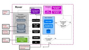
- Rover Architecture
- System design description/depiction
- Perception Subsystem Perception subsystem is the primary way through which our system senses the lunar environment. The subsystem takes input from various sensors/camera and fuses the information to have a complete view of the whole environment. Perception subsystem provides the crucial information needed for following subsystem to take actions.
- Localization Subsystem
- Planning Subsystem
- Pit Modelling Subsystem
| ID | Requirement |
|---|---|
| M.P.1 | Generate waypoints, at-least 30 cm from the edges of the pit, to capture the 360-degree internal view. |
| M.P.2 | Plan to be in detection range (10 meters) of each other every 3 meters |
| M.P.3 | Detect and avoid objects of height > 20 cm, 80% of the time |
| M.P.4 | Detect another rover with a precision of at least 80% up to a distance of 10 meters |
| M.P.5 | Estimate relative pose of another rover with the mean error in Range < 30 cm Yaw < 4° |
| M.P.6 | Co-localize with a maximum error of 5% for every 100m distance traveled |
| M.P.7 | Capture pictures of a 2-meter diameter pit till a depth of 0.5 meters |
| ID | Requirement |
|---|---|
| D.P.1 | Generate waypoints with an added constraint of changing the illumination of the pit, at least 30 cm from its edges, to capture the 360-degree internal view |
| D.P.2 | Detect, plan locally and avoid objects of height > 20cm, 99% of the time |
| D.P.3 | Generate a 3D model of the pit with a maximum point to point distance error of 5% |
| ID | Requirement |
|---|---|
| N.F.R.1 | Cover a distance of 1 km in one charge cycle |
| N.F.R.2 | Have a minimum number of additional moving parts |
| N.F.R.3 | Capture, store and publish location-tagged images captured en-route pit |
| N.F.R.4 | Have a manual override (joystick control) for both rovers |
| N.F.R.5 | Be extendable to a system with more than two rovers |
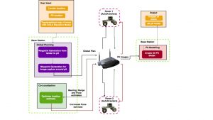

Astrobotic our customer, provides the system with the initial information to begin the mission of co-robotic lunar exploration and pit modelling. This initial user information comprises of the lander’s location of landing on the moon, location of the pit which we wish to model, the sun azimuthal data and the topographical map of the lunar environment.
This data is provided to the base station and a cost map is created. This cost map is in turn used for creation of the global plan. Path way points are generated around the pit as part of this global plan. The global plan is then communicated to the two rovers. One thing to note here is that the two rovers may receive different global plans. The above architecture highlights in detail the flow of rover 1, a similar flow of actions take place for the second rover as well.
The rover estimates its own pose and senses the environment- to identify inaccessible areas and the other rover. This detection of the other rover can then be used to estimate the other rover’s relative pose in the form of range and bearing. The thing to bear in mind here is that this estimation of relative pose doesn’t happen continuously but is rather intermittent. The second rover also estimates the first rover’s relative pose and communicates it back to the first rover. This added relative pose data aids in co-localization of the rover along with the perception and self-pose data, which the rover continuously collects.
This in turn assists the rover to plan locally. The rover then follows this local plan to navigate it’s way to and around pit- making sure to reach the feasible pathway points generated by the global planner. The rovers keep clicking beautiful pictures of the moon on the path to pit after a fixed time interval. On reaching the pit, the two rovers circumnavigate around the pit and pause at the waypoints to capture images of the pit. These pictures are stored and tagged with their corresponding localization data i.e. the location of the two rovers when the snapshot was captured. The process repeats until the last waypoint is reached.
After this process terminates the rovers communicate back to the base station the images they captured on their lunar voyage. These are then processed at the base station to create a 3D model of the pit.
The final output of the system are the images captured on the moon and the 3D model of the pit.
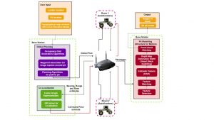
This section highlights the cyberphysical architecture of the system. It particularly highlights in detail each of the functions mentioned in our functional diagram and our technical approach towards achieving those functions. In order to take input from the user, an interface is defined to take the Lander and Pit location. Moreover, LRO LOLA Elevation model will be used to generate a global path from lander to the pit.
In terms of sensors and computation, both our rovers will be homogeneously equipped with following sensors: –
1. Stereo Camera – Used to render the 3D view of current scene to detect obstacles. The high resolution of the camera will also be used to capture HDR images of the pit which will be used to create a 3D model on our base station
2. Catadioptric Camera – Used to estimate the relative bearing of other rovers.
3. Ultra-wide band Sensor – Used to accurately measure the range of other rovers
4. Encoder – Used to estimate the motion and current location of the robot.
Above sensors will help in estimating current pose and 3D view of the environment which will be used by planning as well as localization system. Wi-Fi will be used for communication between Rover to Rover, Base Station to Rover and vice versa.
Data readings from the range and bearing sensor, location estimate from wheel encoder and location estimate from visual odometry generated from sequence of images will be fused together using Extended Kalman Filter to get an accurate estimate of rover’s location.
With location from localization subsystem and scene understanding from our perception subsystem, our local planner will fuse the information with global planner and generate an optimal path to reach the next waypoint.
Once all the waypoints around the pit are reached, all the images of the pit are transmitted to the base station for publishing over the internet as well as creating a 3D model of the pit. Pit modelling will be done using Structure for Motion algorithm using known camera poses. With accurate estimate of stereo baseline and camera pose, we expect to generate an accurate 3D model of the pit.

The perception subsystem generates the above outputs using a sensor rig which consists of camera sensors for perceiving current environment, TOF sensor to detect range of the other rover and a catadioptric sensor to estimate the bearing of the other rover.
The localization subsystem is core of our system because of two main reasons. First, Global Positioning System (GPS) is not present on the Moon and to conduct any autonomous exploration, localizing the robots in the system is necessary. Second, accurate models of the pit can only be achieved if the camera poses for the images are known with sufficient accuracy. Inputs to the localization subsystem are wheel encoder readings, rectified sequential images from camera to calculate visual odometry, range and relative bearing of the other rover (received via Wi-Fi). The output of the system will be an accurate location of the rover.
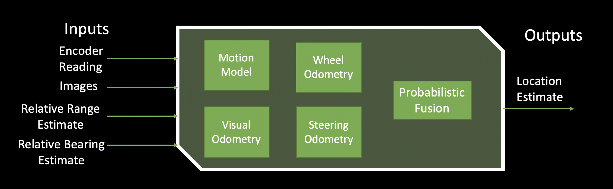
The project aims to achieve this by getting an initial estimate of rover’s location by using established wheel odometry. In the lunar environment, wheel odometry fails to give an accurate location estimate because of tire slippage on the uneven terrain. The project aims to implement a novel idea of colocalization to improve the above estimates. Our colocalization subsystem will handle the above problem by considering each rover as a static landmark and detecting the relative range and bearing. The subsystem finds the best likely pose of the rover using above data.
Once we have the location estimate both from relative measurement (co-localization) and wheel/visual odometry modules, measurements will be fused using Extended Kalman Filter to get a final estimate of location. Duration after which location estimates are calculated can be tuned to further bring down the localization accuracy under acceptable limits as mentioned in our requirements.
The Planning subsystem is divided into mainly global and local planning which works in two different scenarios 1] Planning path to the pit 2] Planning path around the pit. Inputs to planning system are images of current environment to detect obstacles, rover’s current location, topographical map of the Moon and destination/next waypoint. The output of the system will be a global plan or a local plan to reach the destination/next-waypoint taking into consideration all the constraints.

Local planner is primarily responsible to fuse global planner with the local environment and avoid obstacles of height more than 20 cm and slope of gradient more than 20 degrees. Local planner does this based on the cost map generated by perception subsystem. Our local planner also takes care of re-planning the path to the next waypoint based on the improved localization.
Another interesting aspect of the local planner is to aid the localization subsystem to function optimally. The planning algorithm will have an added constraint to facilitate colocalization by selecting rover paths such that they are always in the communication and detection range of each other. Periodically, localization subsystem will make use of relative range and bearing estimate of other rovers as well as pose estimate from another rover to optimize the location estimate.
The Pit Modelling subsystem is on our offboard computer which receives the location tagged high resolution images of the pit and generates a highly accurate 3D model. The subsystem interacts primarily with the data collection subsystem on the rovers through the Wi-Fi module. Once all the waypoints/viewpoints are visited with required accuracy, all the data collected by the individual rovers are sent to the base station for computation; output of which will be hosted on our website.
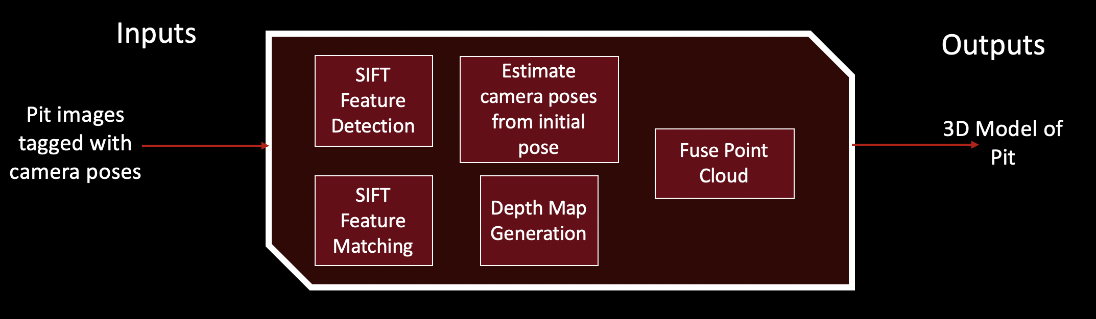
In general, the pit modelling subsystem will be primarily based on Structure for Motion algorithm with known camera poses. The subsystem will take the advantage of accurate camera pose estimates through localization subsystem reducing computation power and time needed to use triangulation to calculate camera poses. Having pre-calculated camera poses with the choice of full frame high resolution camera, our system will be able to render accurate 3D model of the pit. Through our planning subsystem, we also have the control on maintaining minimum base line required between two camera and maximizing overlap between the images taken by two rovers. By tuning these planning constraints, we expect to settle down on an accurate reconstruction with maximum coverage of the pit.