
7th January 2019
Sensor Tower CAD design and Fabrication

The sensor tower was first modeled in Solidworks and then was fabricated using 80/20. The sensor tower contains placement of various sensors- the ultra-wide band range sensor, the 360° fish-eye, downward facing fish-eye (not shown in diagram) and the catadioptric camera. The Solidworks model above highlights the field of view of the each of these sensors. The height has been chosen appropriately to ensure optimum field of view as per our requirements.

15th January 2019
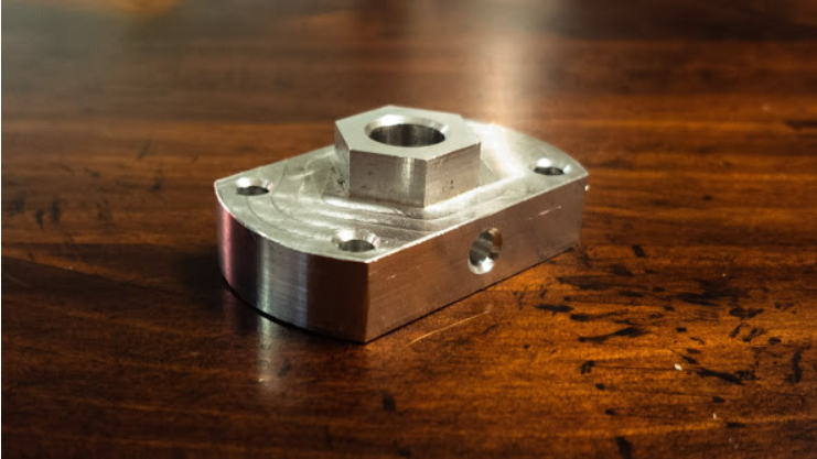
Part of the axle which interacts with the wheel hub was quite prone to shearing which used to render the rover immobile. The fixing of the same was really time-consuming as well. So we designed and fabricated a new attachment for connecting the axle to the wheel hub.
30th January 2019
Our rover is an all-terrain all wheel drive. It has two sets of differentials and double ackermann steering drives for sharp turning. In the previous experiments, the brass pinions on the ackermann drive motor have broken frequently. On the given date the issue was classified as a major risk to the project and it has been decided that a new sets of rovers will be designed during the next two months. The new sets of rovers are still under construction. 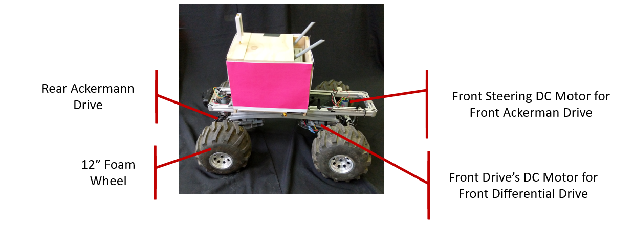
22nd April, 2019
On studying the events when the shearing of the steering brass pinion occurred, we identified that torque applied to the steering mechanism beyond the extent of the steering limits was causing the brass pinon to sheer. Since brass pinons only cost $10, we decided that those would be accepted as the point of failure. To further reduce the risk of unnecessary force beyond the limit of steering, we decided to put limit switches on the steering mechanism. These are electronically controlled by the processor and cut off current to the motor when steering input is provided beyond its limits. This, however, is not robust to the forces of nature.
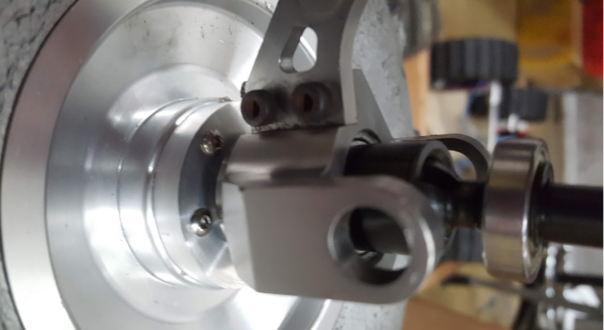
Figure below depicts the redesigned chassis of the robot. We now have both, front and rear, steering motors accessible without having to dismantle any part of the robot. Furthermore, it takes a total of 4 screws to dislodge the steering motors from the rack and pinion setup. Once out, we can swap out the brass pinons and put the mechanism back together.Since we had some changes in the chassis, we then had the opportunity to rethink some other design aspects of the robot to, first, make a more reliable and safe platform and second, customize it taking into account the scope of our project. We then went on to redesign the upper decks of the robot that will house the sensors, power distribution system, battery compartment, and electrical safeguarding.
Since we had some changes in the chassis, we then had the opportunity to rethink some other design aspects of the robot to, first, make a more reliable and safe platform and second, customize it taking into account the scope of our project. We then went on to redesign the upper decks of the robot that will house the sensors, power distribution system, battery compartment, and electrical safeguarding.
In the earlier Autokrawler, the battery would reside on a flat surface on the robot, not fixed to any part of the robot. This poses a risk of falling off the rover while driving through rough terrain and is extremely dangerous for the operation. We designed a new compartment below the main frame of the robot which can comfortably house the batteries. In this compartment, the battery sits firmly and is restricted to move around. It is centrally placed concerning the axis of the robot and by being below the chassis and weighing approximately 5 Kg, brings the center of mass of the entire robot low.
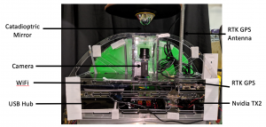
The decks house the various computing devices, sensors, and electrical components. The chassis houses the motor controllers, IMU and fuse block. The other elements such as TX2, WiFi router, RTK GPS and PointGrey camera sit on the upper decks. The antenna for the RTK GPS is moved to the topmost position on the rover. The catadioptric camera system was custom made for our project. The camera sits on a rail in front of the mirror, thereby making it possible to tune various parameters of such as focal length, distance from mirror and field of view captured by the camera.
