

27th March 2019
Conceptual Design of PCB
For our Robotic System, we required an electronic circuit for the following two cases:-
1] Power Distribution Unit – Power distribution unit provides power to all our electronic components including the processor, sensors. Our system includes 24V to 12V converted as well as 12V to 5V converted which are needed for various electronic circuits. In our conceptual design, we list down all our electrical subsystems and their power requirements to facilitate our PCB design
2] Undervoltage protection circuit – While developing our robotic system, we have blown two batteries because of elongated use. We realised the importance of having an under voltage circuit and thus decided to build that.
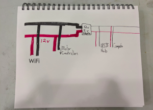
Below is our hand drawn version of the power distribution circuit.
8th March 2019
Schematic Circuit Diagram
We designed the first version of our PCB corresponding to our initial conceptual design. It consists of the following components:-
1] LEDs to indicate the power flow in the given sensor
2] Fuses to protect the circuit in case the sensor pulls high currents
3] 24 V to 12 V converter and 12 V to 5V converter
4] Relay and Beeper for undervoltage protection circuit
5] Connectors for batteries and sensors
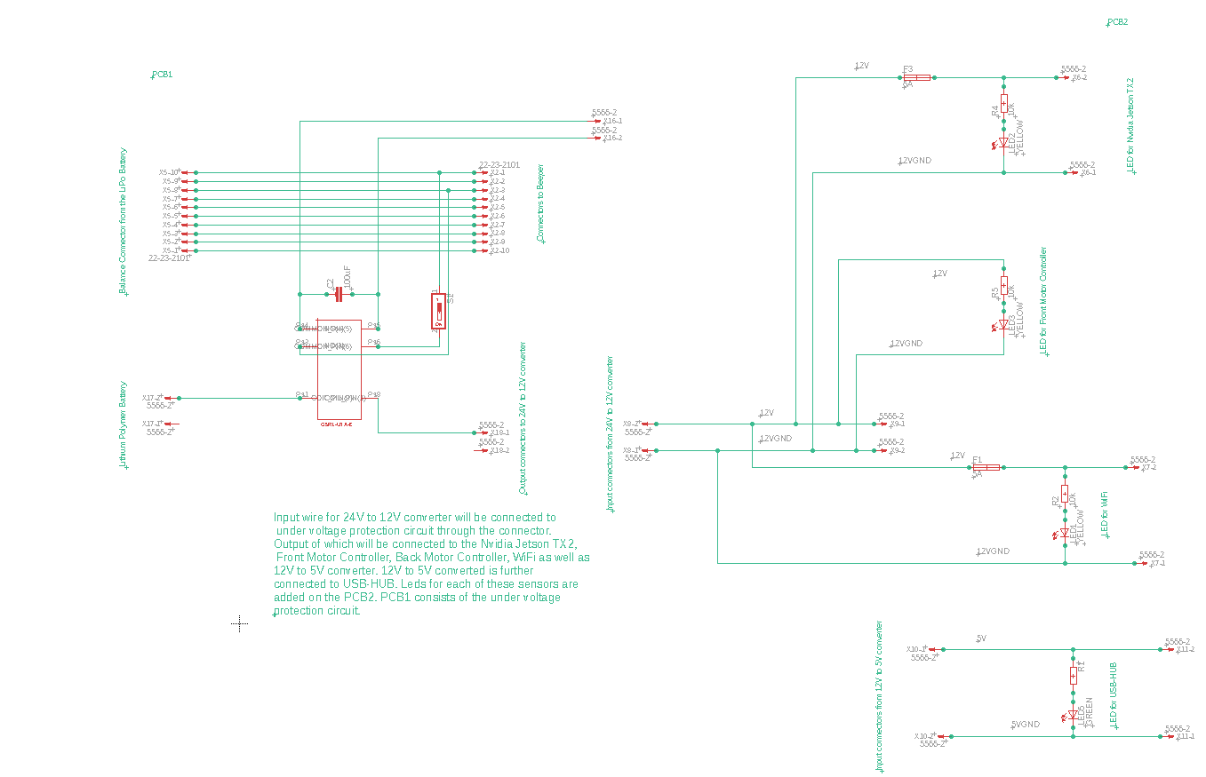
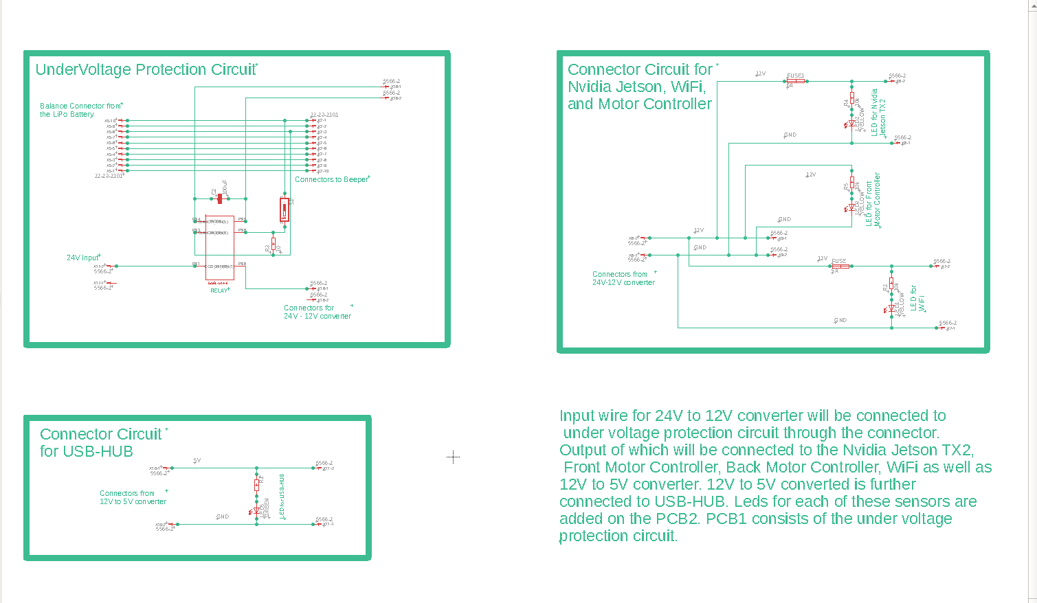
Below is the first version of our schematic diagram made in Eagle software
20th March 2019
Schematic Circuit Diagram and Layout
We iterated the first version of our schematic diagram and laid out the layout of the PCB. We also created an eagle library for specific relays we need for undervoltage protection circuit.
Below is the updated version of our schematic diagram and layout of the PCB
6th April 2019
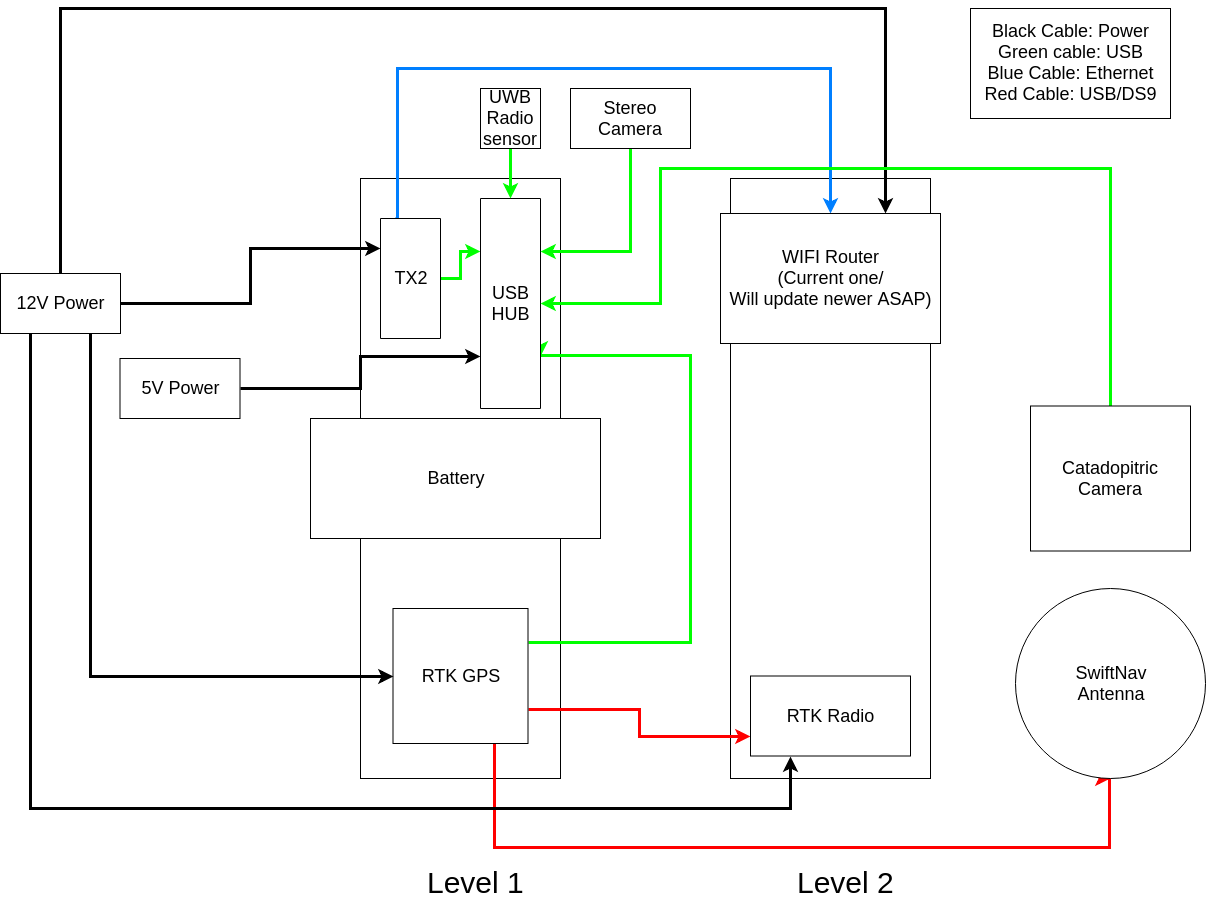
Wiring Diagram
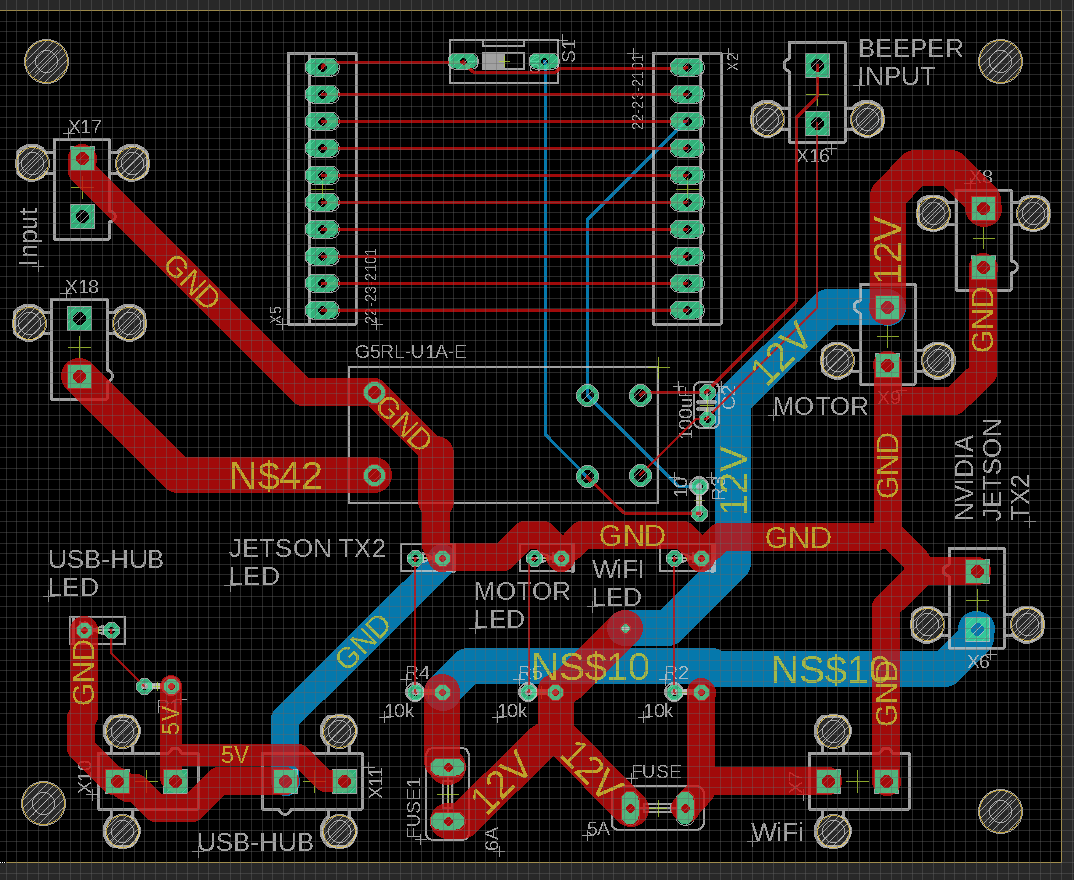
Here’s is our first version of component placement and wiring required.
17th April, 2019
Since we have a hoard of new sensors onboard, we had to manage the power distribution throughout the rover. Learning from the design issues with electrical components in the previous design of the Autokrawlers, we noticed that the main fuse was attached in the circuit after the step-down converter from the battery. We made sure that the fuse and battery monitors are right after the battery, thus preventing any devices from getting damaged by fluctuations from the battery.
After understanding the current ratings of all the new devices on the system, we introduced a terminal fuse block which houses individual fuses for each of the components. Furthermore, to protect the LiPo battery from damaged due to under-voltage, we designed a PCB which works in conjunction with a standard battery beeper to cut off the current drawn from the battery in case the voltage of any cell goes below the threshold.
