Sensor Pod Design
Progress Review 1
The sensor pod is the main payload for the AACAS system. It connects the lidar, camera, processing board, power distribution, and battery to the drone. The sensor pod uses two tiers to compactly house each of the components. The bottom tier holds the lidar, lidar interface box, camera, and potentially the battery. The top tier holds the power distribution board (not shown) Xavier, and has extra space for wire management.
In the future, we plan to create a nice casing for the Xavier. As a fit test, we 3D printed a case. Despite some filament failure in the final layers, the casing effectively houses the Xavier.
Progress Review 2
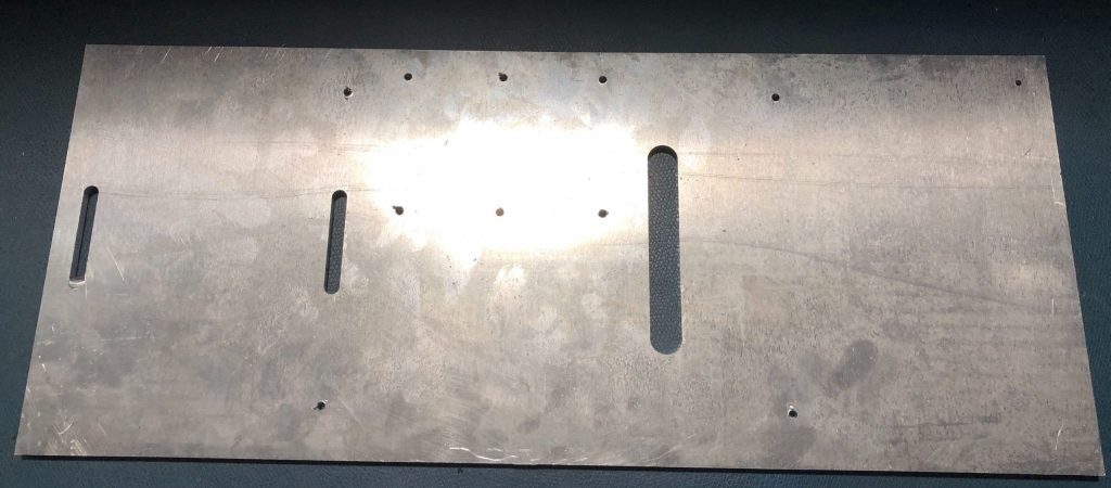
The bottom plate is required to begin preliminary work on the sensor fusion system. We machined the bottom plate out of 1/8″ thick aluminum. The plate has mounting holes to connect the top plate standoffs, camera mount, interface box, and lidar. The lidar also has two holes to press-fit alignment pins.
Progress Review 3
To finish the bottom plate, we machined a small angle bracket out of aluminum to connect the Intel RealSense camera to the bottom plate.
Progress Review 7
With CMU campus being reopened, the machine shop became accessible. In this review, we machined the top plate of the sensor pod out of a 3/16″ thick aluminum sheet. The part was cut out using a CNC router.
Progress Review 8
In this review, we finished the assembly of the full sensor pod. The image below shows the top plate with the batteries, power board, and Xavier mounted. The bottom plate as previously described mounts to the top plate via 4 hex standoffs.
Power Distribution Design
A large amount of power is required for both the sensors and the main computer for this project. Currently, the Lidar system needs ~35W on startup and the computer, a Jetson Xavier, needs ~30W. The camera used for our project (Intel real sense) is low enough to be powered with a USB from the Xavier. This amount of power needs a separate power distribution board (PDB) to regulate the voltage and current and provide over voltage (OVP) and reverse voltage protection (RVP).
Additionally, the Lidar and computer are powered separately to prevent the high inductive motor in the Lidar from effecting the computer. This reduces the risk the computer will fail during flight. The schematic of the PDB is shown below:
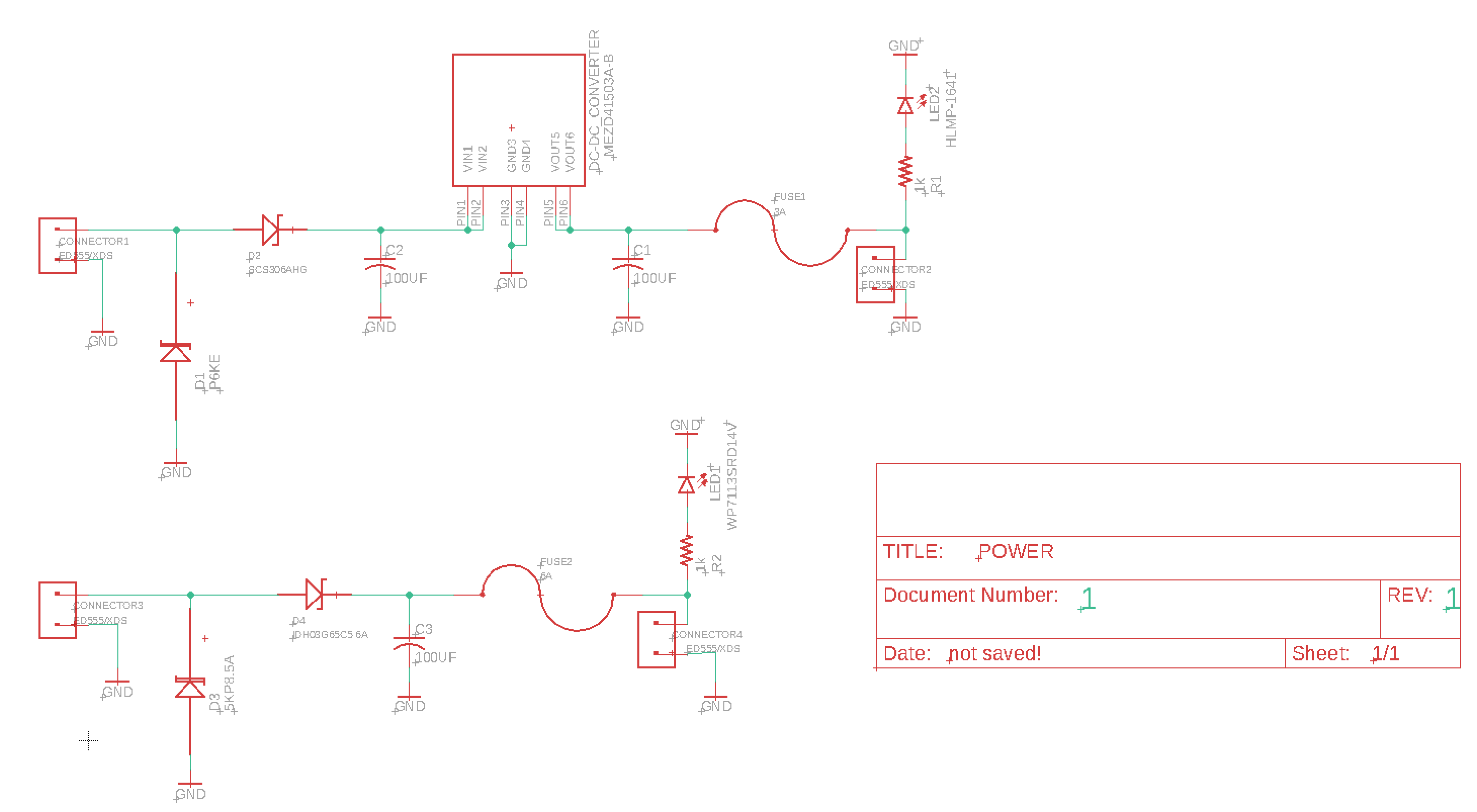
The above schematic shows the two separate power systems. The top system converts a 3000mAh 7.4 LiPo battery to 12V and 3A output with OVP and RVP. the bottom system uses the Matrice 600 XT30 port as input with OVP and RVP to power the Xavier. Both systems also include fuses to prevent excess current from damaging our sensors.
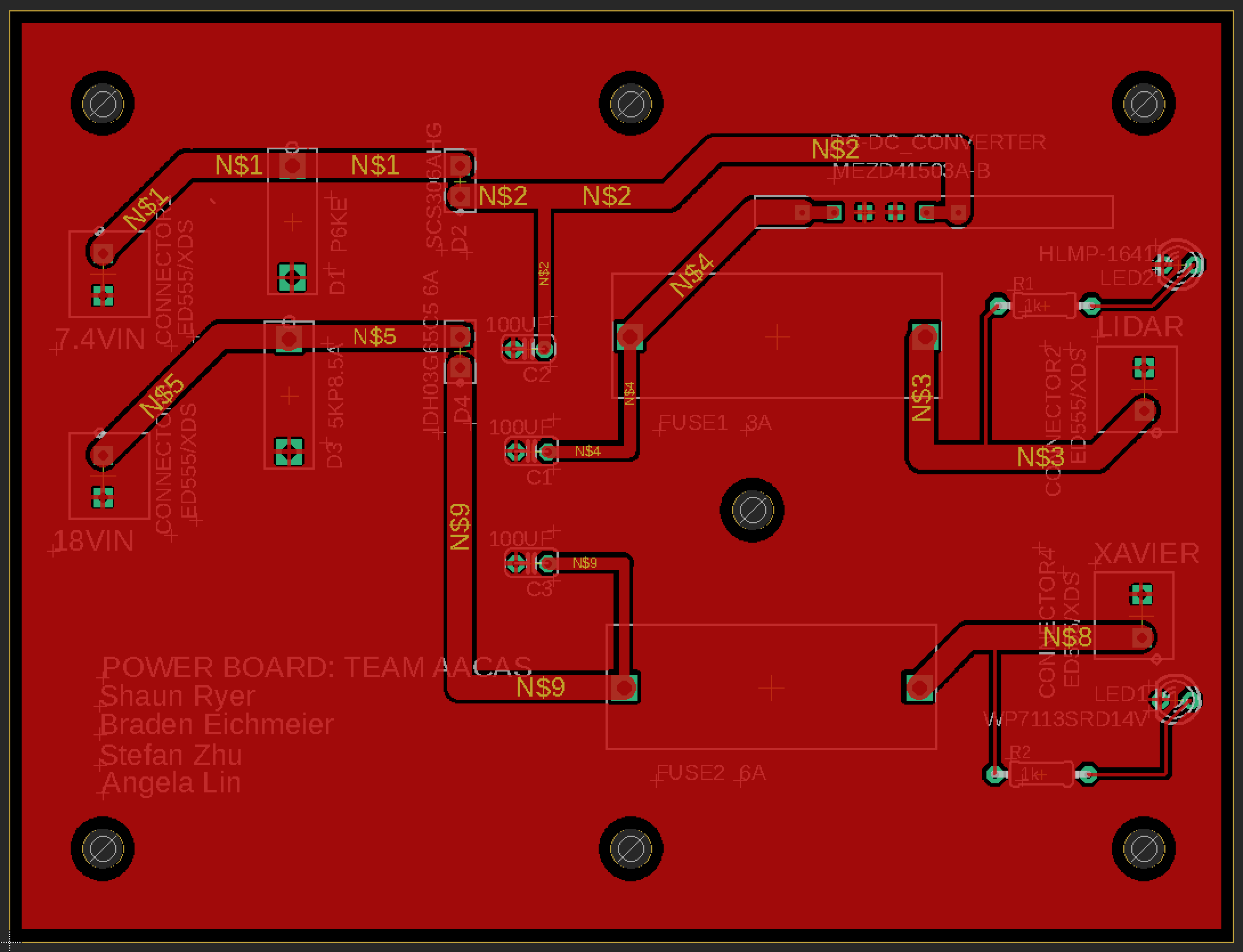
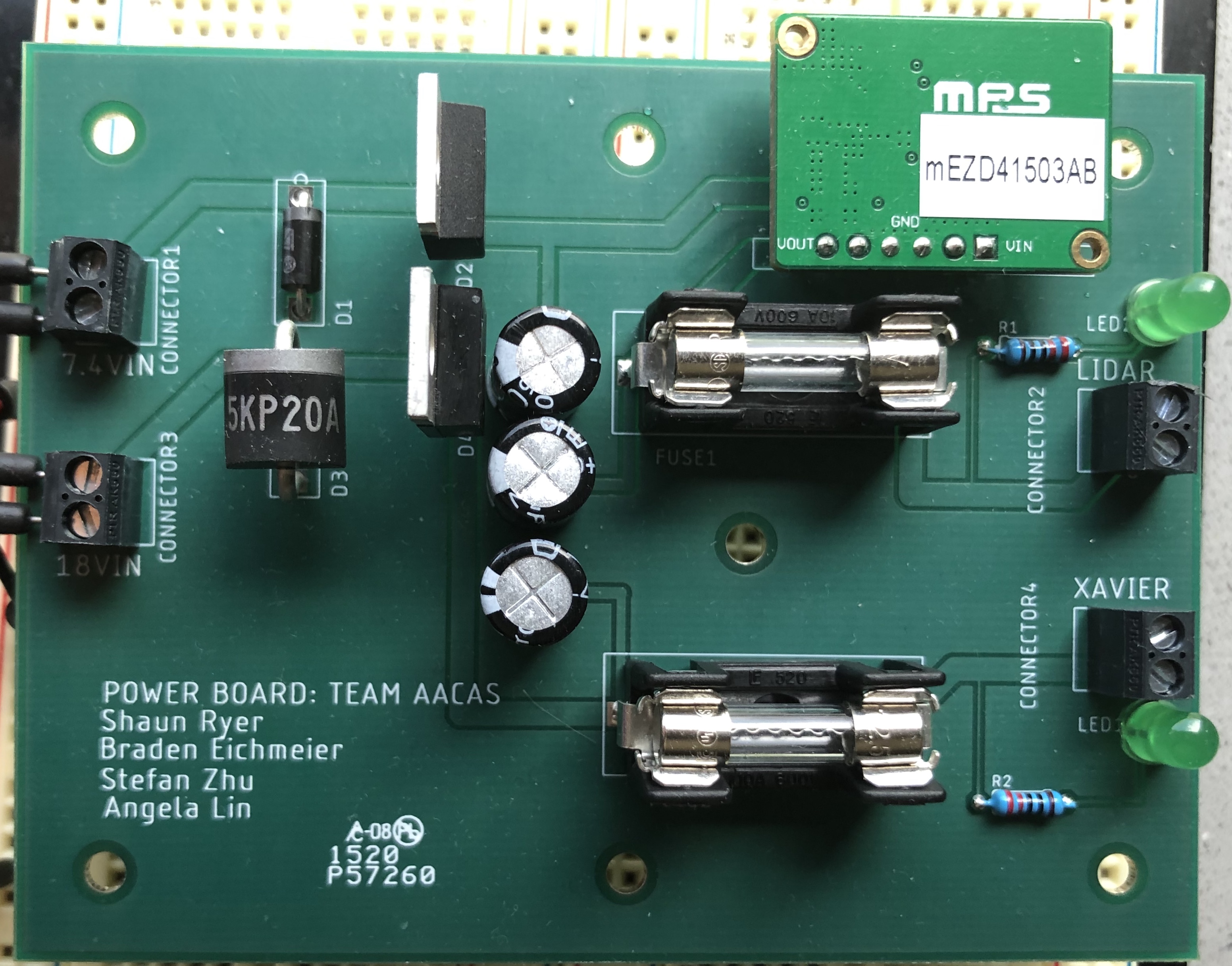
The layout and final product of the PCB is shown below.:
I/O Design
The Input/Output hardware connects all the sensors to the computer, and from the computer to the DJI drone. USB-TTL Cable connects Matrice Lightbridge to Jetson Xavier, transfering either motor commands from the Xavier to the Matrice 600 or data from IMU/GPS. Data from the Intel Realsense is supplied through USB-C/USB3.0 from Jetson Xavier. The Lidar communicates with the Jetson Xavier over ethernet cable.