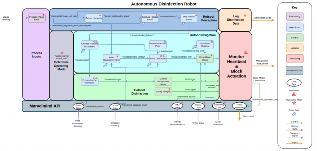
Prior to starting development of the software components of Salus, we created a ROS architecture flowchart to detail how each of the components will connect into the system as a whole. This made integrating components and subsystems much easier as we began development and integration. The figure below shows this ROS architecture, which includes the components from the Functional Architecture and rostopic names for each of the topics being published by each component.
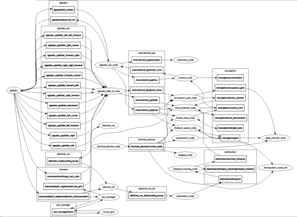
After developing the components of each of the subsystem, we were able to integrate the software components without too much trouble. The figure below shows a RQT graph that was generated while running the full software system in simulation using Gazebo.
The tactical planner is responsible for keeping track of the operating state that Salus is in at any given time. This was achieved by building a finite state machine, as shown in the figure below. Each operating mode (i.e. state in the state machine) is performed by one of he subsystems. The subsystems will be responsible for requesting a transition to the next state whenever the transition criteria are met.
