Design
The purpose of the indoor navigation subsystem is to move the robot from its current pose to a pose in which it can disinfect a hotspot. This subsystem will receive hotspot pose estimates, select a hotspot to pursue, and control the robot’s differential drive motors to navigate to the hotspot while avoiding static obstacles along the way.
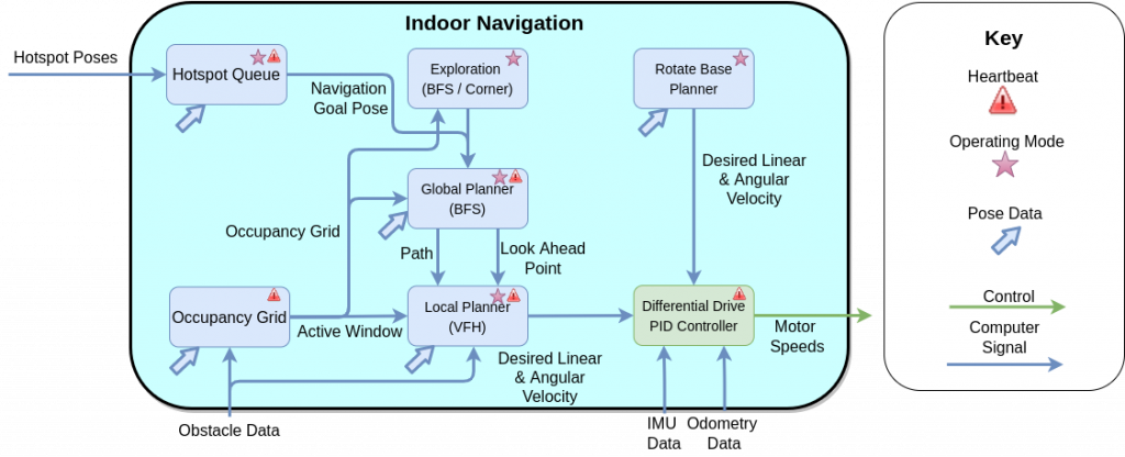
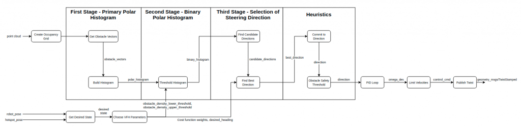
The local planner is inspired by the VFH+ algorithm, which creates a polar histogram of obstacle densities surrounding the robot. The polar histogram is then turned into a binary histogram by applying an obstacle density threshold. Finally a cost function is used to select the best steering direction. The local planner then applies some heuristics specific to Salus’ use case. The final desired yaw is converted to a desired angular velocity with a PID loop. The local planner also adjusts various parameters based on its distance to the goal.
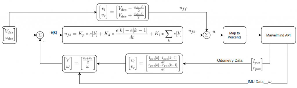
The differential drive controller takes the desired speed and desired angular velocity from the local planner and outputs motor speeds in percents to be actuated on the robot. The controller uses a feed-forward control term using the differential drive kinematic model, and a PID feedback loop. The feedback comes from odometry and IMU data from motor encoders and an IMU sensor on the robot.
Modeling, Analysis, & Testing
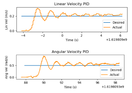
Due to a delay in the Marvelmind robot base, a model of Salus was built in Gazebo for testing the indoor navigation subsystem. Testing was performed incrementally, starting with the differential drive PID controller. To test the differential drive PID controller, desired linear and angular velocities (which normally come from the local planner) were sent as an input to the controller. The desired linear and angular velocities versus the actual linear and angular velocities of the Salus were plotted to check the transient response. Results of one such test are shown in the image below. The graph shows that the controller is underdamped, but settles to the desired velocity and angular velocity within a few seconds.
Next, the occupancy grid and the local planner were tested. The occupancy grid was tested in isolation by publishing fake LiDAR data and visually checking that the cells of the grid were updated correctly. The local planner was then tested while Salus was stationary with fake LiDAR data being published to the occupancy grid. This test ensured that the VFH algorithm was choosing a direction that avoided obstacles while moving towards the navigation goal.
Finally, after each component was performing as expected in isolation, the full indoor navigation subsystem was tested. Various gazebo environments were created with obstacles in the path between Salus and the navigation goal. The video in the link below shows the results of one such test. Salus was able to successfully navigate from the start position to each of the goal poses while out-performing the requirements in MPR-5.
Navigation Full System Testing – Video
After the Marvelmind base and IPS were fully functioning and integrated with the indoor navigation subsystem, the navigation software was tested on the Marvelmind robot. Initial testing involved point-to-point navigation while avoiding obstacles. During these tests, we observed the final pose error of Salus to make sure it met PR6-M. Eventually we were testing Salus in a more cluttered environment than originally intended, which prompted the addition of the global planner. Unit tests were also added throughout the fall semester to test individual functions within the indoor navigation subsystem.