Design
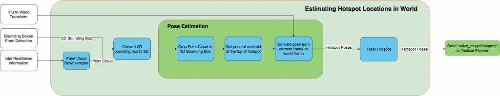
The goal of the Hotspot Pose Estimation system is to take in bounding box information and depth information and convert it to a pose in world coordinates. The bounding box comes from the Detection subsystem. The estimation system converts the 2D bounding box from Darknet in a 3D bounding box. The depth image comes in through the Intel Realsense 435i camera. The depth image gets downsampled and converted into a point cloud. The estimation system uses the point cloud and 3D bounding box to get the position and orientation of the hotspot. It then passes it to the Track Hotspots node which uses a Kalman Filter to maintain knowledge and reduce noise. This is then passed off to the Tactical Planner. Figure 1 below depicts the the process described.
Implementation
Point Cloud Downsampler:
The point cloud downsampler uses the depth image from the Intel RealSense camera to create a point cloud using a ROS nodelet. This point cloud is downsampled to make sure the estimation system can maintain and update hotspot positions at a frequency of 10 Hz (PR4-M).
Hotspot 3D Bounding Box Converter:
The purpose of the 3D bounding box converter is to transform the 2D bounding box from Darknet into a 3D bounding box we can use with the point cloud to segment out the hotspot. It uses the point cloud to determine the z-coordinate of the hotspot.
Hotspot Pose Estimator:
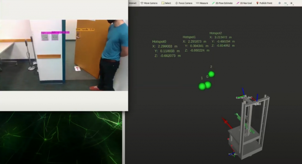
The hotspot pose estimator takes in the 3D bounding box and a downsampled point cloud generated using the Intel RealSense depth image. It then crops the point cloud to the dimensions of the 3D bounding box and computes the centroid of the top of the object. Finally, it converts the centroid into the world frame using the IPS to World transform and outputs the pose. In addition, it determines the orientation of the hotspot by computing the surface normal of the cropped point cloud.
Hotspot Tracker:
The purpose of the hotspot tracker is to maintain history of our hotspots pose and reduce the uncertainty in pose due to noise/bad frames. It uses Kalman Filter with Mahalanobis Distance to smooth the hotspots’ estimated pose.