Design
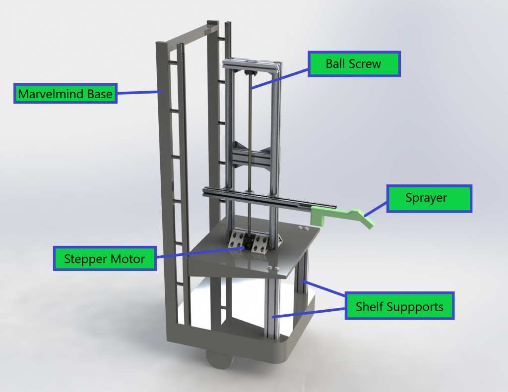
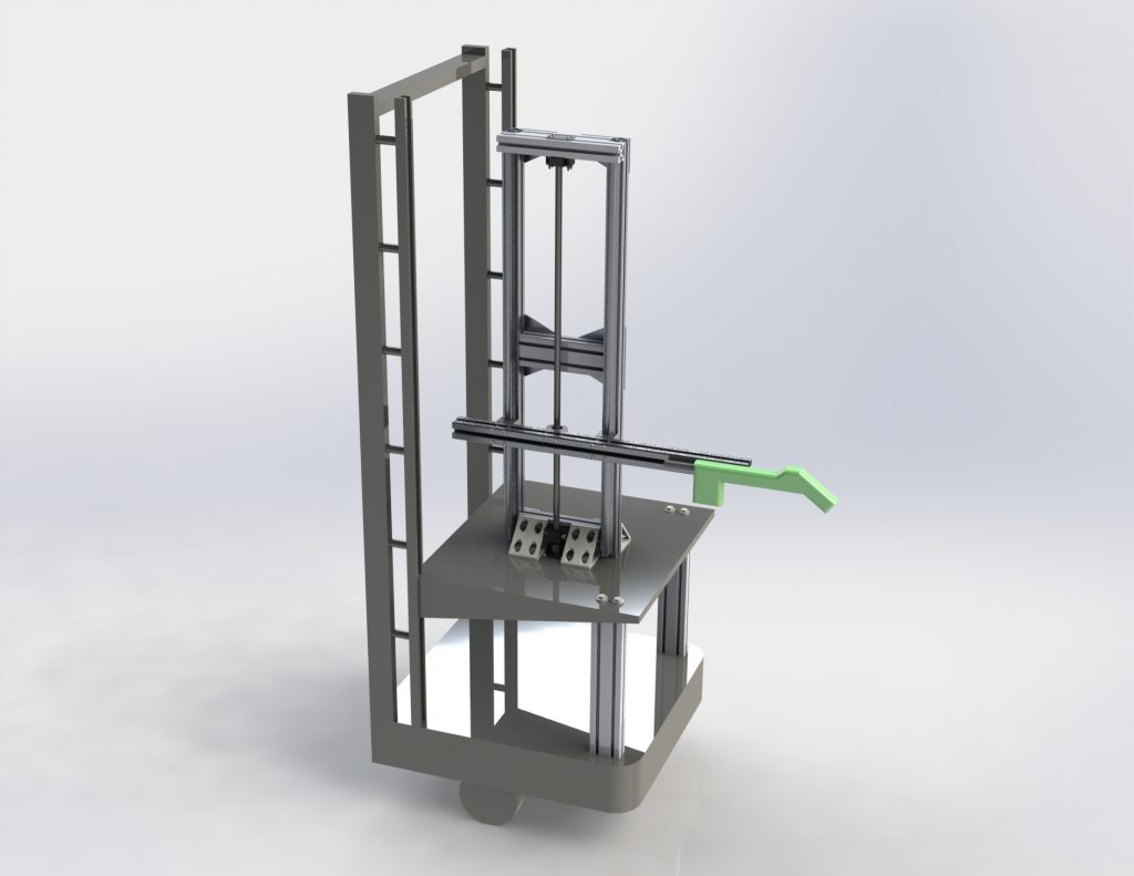
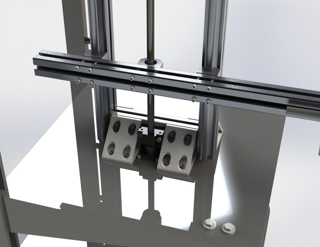
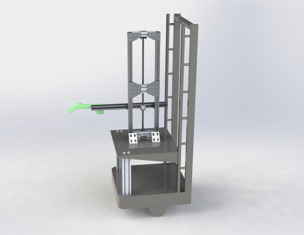
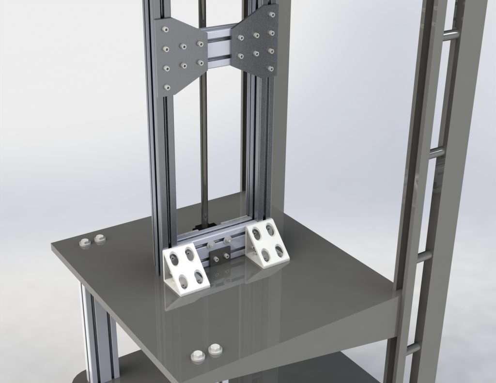
The manipulator subsystem consists of a single prismatic joint to adjust the height of the electrostatic sprayer. This will allow us to disinfect a wide range of surfaces. The design goals for this subsystem were to be able to adjust the height of a 5 kg load to desired positions in a 90 cm range. The entire assembly was also constrained to 25 kg in mass total, to minimize the difficulty in mounting it to the robot base and the effect it had on the robot’s dynamics. The assembly is centered around a 1-meter long ball screw that is driven by a stepper motor. The frame consists almost entirely of aluminum extrusion, with two linear rails added to help the screw support the load. A CAD model of this subsystem was created in Solidworks, and several renderings of it (mounted onto a sketch of the robot base) can be seen below:
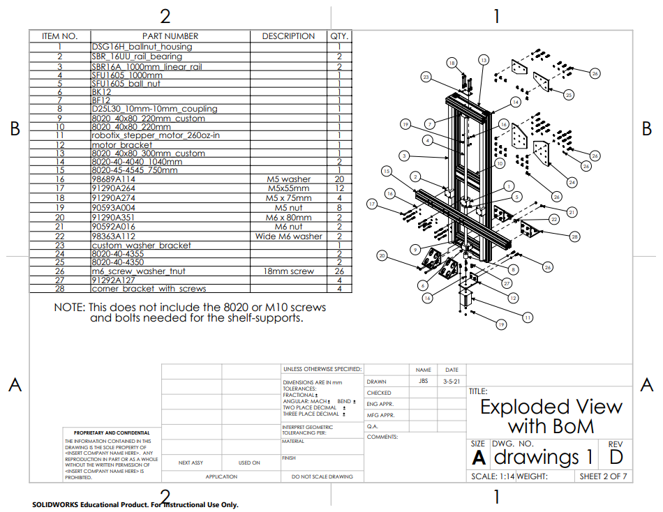
The engineering drawings for this assembly can be found here. The aluminum extrusion was all acquired on https://8020.net/, and all hardware (screws, nuts, washers) were found on https://www.mcmaster.com/. The full bill of materials can be seen below:
Fabrication
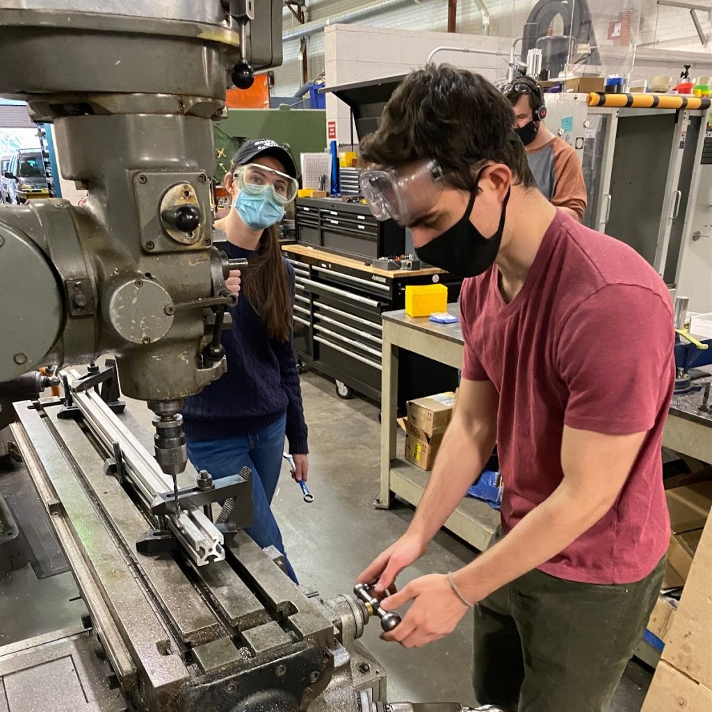
Nearly every part in the assembly was a stock part that at most required being cut to size and having a few holes drilled into them for connecting to other parts. There are also two limit switches on the assembly, one at each end of the travel of the ball screw. These are included to prevent jamming the sprayer arm at either end of the screw, and to provide a means for “localizing” the manipulator’s position on start-up of the robot. There are also two relays – one to make the sprayer start and stop spraying, and another to turn the stepper motor driver on and off. The components were fabricated in the Robotics Institute machine shop, and assembled in the MRSD lab.
The stepper motor that was selected has 260 oz-in of torque which, combined with the 5mm lever arm of the ball screw, gives us a theoretical maximum vertical load of 37.5 kg. Taking into account the friction from the moment arm generated by the load, the maximum load this assembly can handle is 28.1 kg.
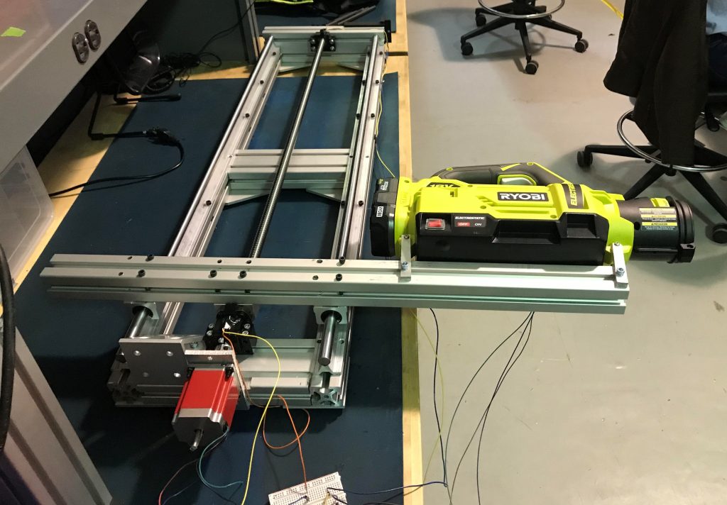
The completed manipulator assembly 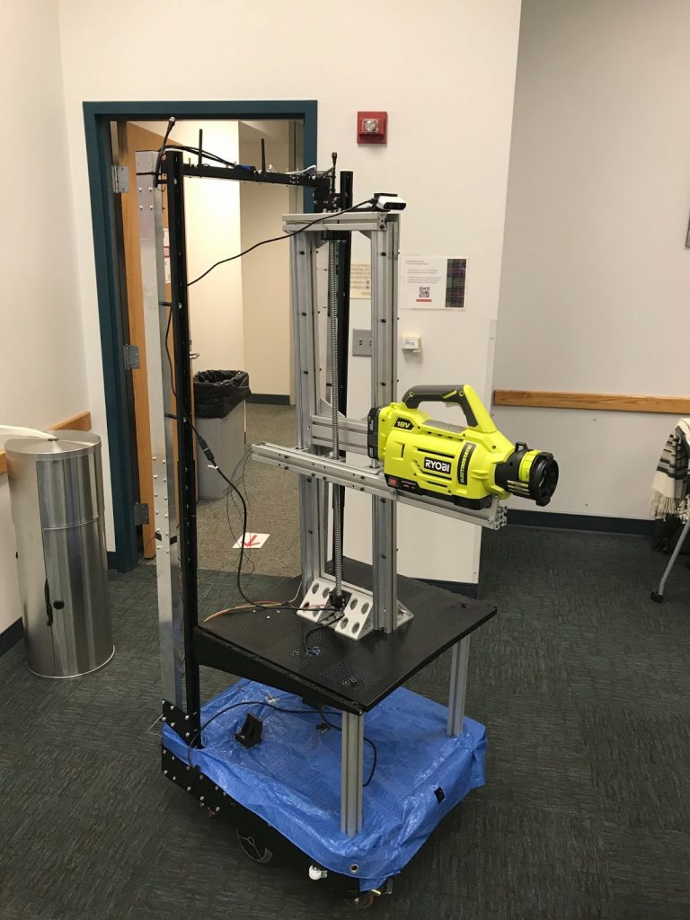
Manipulator mounted onto robot base
The manipulator subsystem met the two system-level requirements it had (MPR6 – move manipulator with 1 degree of freedom & MPR7 – spray hotspots with 0.5 m^2 of coverage), as well as the subsystem requirements listed at the beginning of this page. Two videos of the completed system in action can be found via the links below:
A video of the manipulator being used to disinfect a table can be seen here
A video of the manipulator moving along the entire length of the ball screw can be seen here
Integration
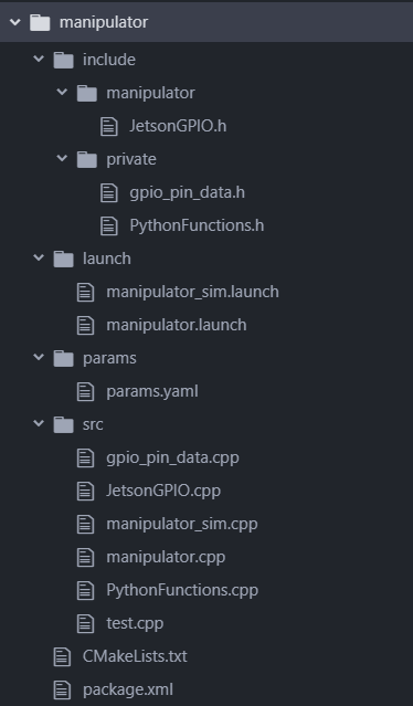
To integrate this subsystem into the rest of the project, a ROS node was created, with the purpose of serving as an interface between the manipulator hardware and the rest of the project’s software. It makes use of an open source C++ library for interfacing with the Jetson’s GPIO pins (link). The file structure for this ROS node can be seen below:
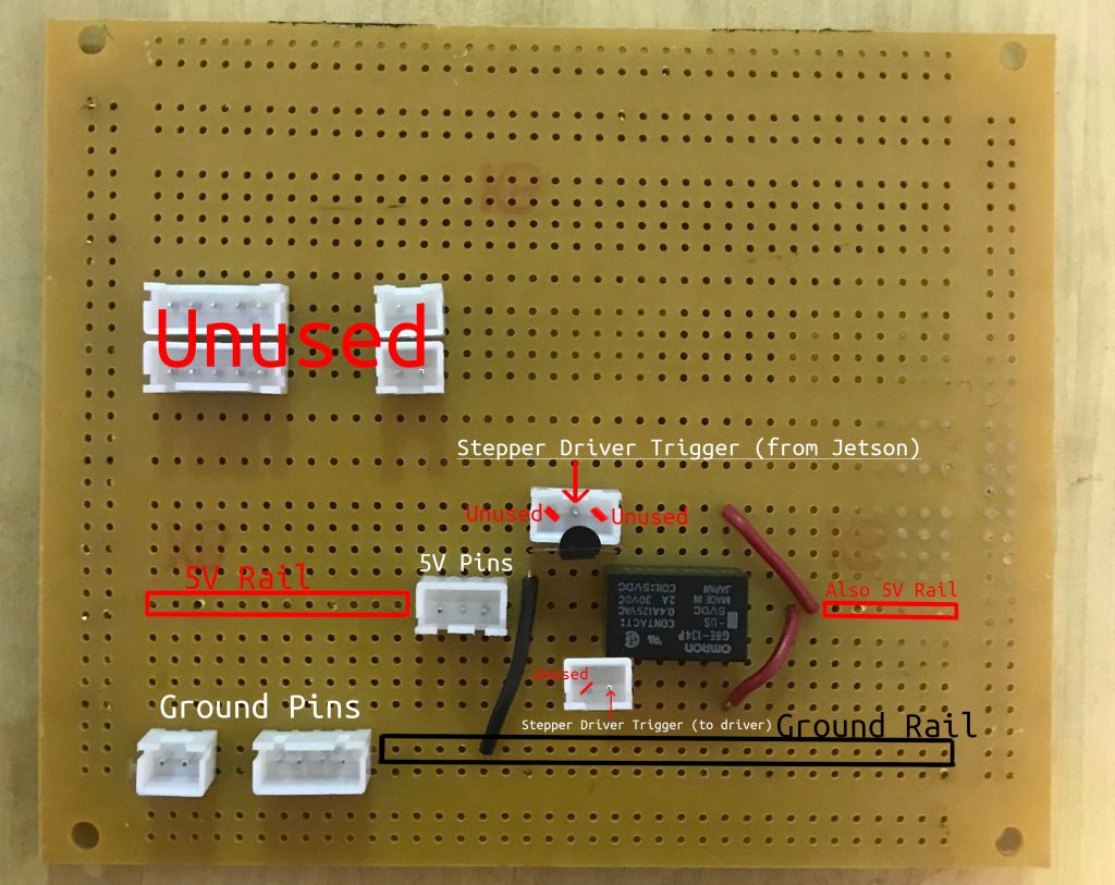
The manipulator circuit, which is responsible from routing signals to and from the Jetson’s GPIOs and the various circuit components of this subsystem (stepper motor driver, limit switches, relays). It can be seen in the Figure below: