System Performance
Fall System Performance Evaluation
The system requirements that we targeted for the Fall Semester were all requirements outlined in the System Requirements post. Function Requirements (and their associated Performance Requirements) 1, 2, 3, and 6 were all validated during the Spring Semester. During the Fall Semester, Functional Requirements 4, 5, 7, and 8 were all tested and validated through the Watchdog Module.
The main metric for validating our system was ultimately to see how accurately we reamed the bone that our surgical plan says that we would. In other words, with our surgical plan, we can construct a desired reamed bone. We can then use this constructed desired reamed bone model and compare it to our actual acetabulum after our system has reamed it. The difference between these models is a direct measurement of how accurately our system carried out the surgical plan. In order to obtain accurate bone scans of our reamed acetabulum, we used a HandyScanner, which scans up to 0.1 mm resolution. The process is shown below.
We performed five tests on five different samples, and the results are shown below:
| Test Number | Maximum Error (mm) |
| 1 | 2.0 |
| 2 | 3.0 |
| 3 | 3.4 |
| 4 | 1.3 |
| 5 | 3.3 |
In 2 out of 5 tests, we were able to achieve our desired reaming accuracy of 2 mm, and therefore were not able to achieve Functional Requirement 5 100% of the time. There are several reasons for this lack of accuracy. While there are many places for tolerance stack up in our system, including camera accuracy and registration accuracy, the largest and most noticeable source of error comes from the mechanical flexibility of our system. Our end-effector has about a millimeter of flexibility, and our arm, because it is a collaborative robot, has much more flexibility. Therefore, it is likely that this flexiblity, in the arm specifically, is a major source of error.
Looking at the results, you can see that the errors are eccentric, which shows that the flexibility caused the reaming axis to shift the moment there were forces radially to the reaming axis. This happens when the surgical plan wants to ream eccentrically to the acetabulum. The arm is unable to remain stiff enough for this surgical plan, and flexes more concentrically to the acetabulum than desired.
We also had another metric on the force that our reamer applies during the reaming operation. Our goal was to apply less than 100 Newtons of force during our reaming operation. From several tests, we determined that the maximum force that we applied during reaming is 62.306 Newtons, with the mean around 37.633 Newtons.
As for the other functional requirements, the Watchdog Module monitered subsystem rate and latencies, and checked to see if subsystems were ever performing slower than expected. Through multiple tests, the Watchdog never reported the Controls Subsystem lagging behind more than 25 ms, validating Functional Requirement 4 (and its Performance Requirements). The Watchdog itself ran at 100 hertz and was also validated to be running at that rate, running at an average of 99.9 hertz. Since the Watchdog Module also published the e-stops for the system, this validated Functional Requirement 8. The UI also runs at 120 hertz, and has been validated to update at this rate, validating Functional Requirement 7.
Spring System Performance Evaluation
Targeted System Requirements
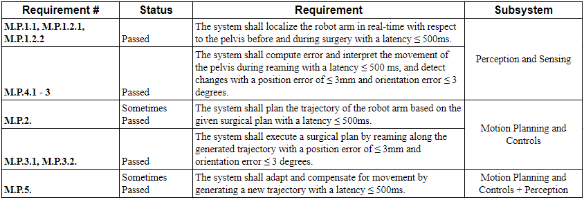
For the Spring Semester, the team had the following set of requirements shown in the table below. Some of these requirements are more relaxed compared to our system-level requirements in section 3, such as the latency requirements for localizing the arm and pelvis being relaxed to 500 ms instead of 50 ms, latency requirements for motion planning to generate a trajectory within 500 ms instead of 150 ms.
Perception & Sensing
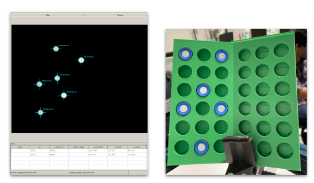
The latency requirements for perception and sensing were met with a current FPS of approximately 54-55. This is about 20 milliseconds. The latency requirements were tested based on profiling the code and using ROS frequency echo commands. The outputs are shown in the figure below.

The pelvis tracker is able to detect error in the pelvis marker within position error of 2mm and orientation error of 3 degrees. The error was calculated based on the 3D-printed part shown in the figure below. Each marker slot is situated 30mm away. A triangular geometry was placed as shown in the figure, on two sides. The two poses were recorded. The test was performed 10-15 times, and the error was calculated.
Planning & Controls
We evaluated the performance of our planning and controls sub-systems using the RPG Trajectory Evaluation toolbox. The toolbox was used to analyze a single trajectory estimate. We provided as input the ground truth and the trajectory followed in reality as estimated by the encoders. The format in which this information had to be parsed was specific, which included the time stamp of a pose, the 3D position of the tool, and the orientation in quaternion. The evaluation criteria were ‘sim3’, which is a similarity transformation for visual-only monocular cases. The results from the evaluation can be found in the figures below.


From the results, it can be seen that our maximum position error (Euclidean) was 2.61 mm. Additionally, the maximum orientation error was 0.241 degrees. Both these errors were within our performance requirement for the Spring semester.
The planning execution time varies between 200 to 700 ms and is highly dependent on the configuration of the robot. Based on the configuration of the robot and its proximity to a singularity, the node takes some time to plan a linear path in Cartesian space which involves computing inverse kinematics at each waypoint in the trajectory. In easier configurations, the planner takes approximately 200ms to plan a linear path. The speed of the planner is also restricted by the hardware limits of the robot. As the Kinova Gen3 is a co-bot, its hardware capabilities are limited.