System Design Description/Depictions
Full System Design
The ARTHuR System starts with a surgical plan, which tells the system where the bone needs to be removed within the acetabulum and where the acetabular cup will be placed. Before surgery starts, the system will have to register the location of the pelvis, using a registration probe with reflective markers on it, which will be localized using the camera depicted in the graphic below. The camera will also be localizing the end-effector of the robotic arm (a Kinova Gen 3 is depicted below in Figure 1), using reflective markers mounted to that end-effector. After doing registration, the pelvis pose is determined in global coordinates with respect to the camera. The surgeon can then move the robotic arm to the site of surgery (the acetabulum) using Free Motion Mode (Gravity Compensation). Then, using this information and the given surgical plan, the robotic arm generates a trajectory and executes the trajectory making sure to not violate force and velocity constraints to ensure safe operation. If the patient moves too much, the camera will detect the movement and another trajectory will be generated to dynamically compensate for that error.

Figure 1: Graphical Depiction of Full System Design (Markers and Full Patient Not Shown)
Subsystem Design
The following sections are the subsystems of our full design. Since these systems are still in development, the depictions here are subject to change as we further implement the subsystems.
Inputs
There are six distinct inputs in the input block. The first is the 3D model of the pelvis, typically obtained from a CT scan pre-operatively. The second is the robot arm description which is used later by Moveit! for inverse kinematics and motion planning. Three sets of passive fiducial markers form the next three inputs. Each marker has an associated geometry [1] which is known beforehand. An example of a reflective marker used is shown in Figure 2. One of these markers is drilled into the patient’s pelvis by the surgeon. Another marker is attached to the base of the robot arm using a mount. The final marker is used to capture key landmarks on the patient’s pelvis and construct a point cloud which will later be used for registration with the pre-operatively built 3D model of the pelvis. The final input into the system is the surgeon’s input, which will control the sequence of operations using the surgeon IO and also exercise the use of an emergency stop button.
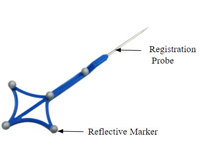
Figure 2: Reflective Marker [1]
The final input is the surgical plan in the form of the 6-dimensional acetabular cup pose which the surgeon decides prior to the surgery.
Perception & Sensing
The sensing module is primarily composed of the joint encoders used to compute the joint positions of each joint of the arm. The marker positions are determined using the Atrycsys Sprytrack 300 camera, which is our primary sensing component. This will be securely mounted to externally overlook the arm and the pelvis during the surgery.
The Sprytrack 300 camera [2], as shown in Figure 3, forms the primary sensing component. Its operation is summarized in a flow diagram as shown in Figure 4. The pose of the end effector pose is updated using the robot arm marker’s pose combined with encoder data from the robot’s joints. The Sprytrack 300 camera is composed of two cameras designed to detect and track 6D pose of fiducials with sub-millimeter accuracy in real-time video streams. The IR Illuminators first emit IR light, which is reflected by passive markers. Sprytrack 300 then detects the reflected light and transmits this data to the host computer. The 3D position of each fiducial is computed and matched to the marker geometry and the rigid body 6D pose is computed for user post-processing.
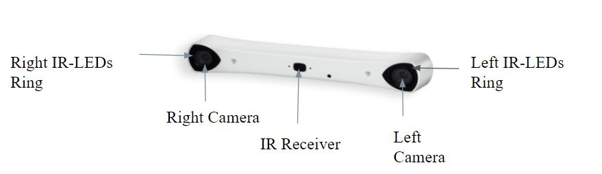
Figure 3: Sprytrack 300 Camera [2]
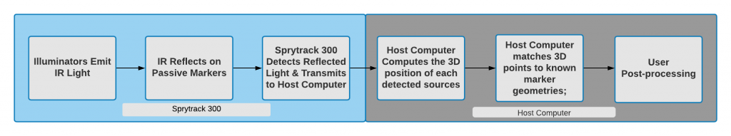
Figure 4: Functional Flow Diagram of Sprytrack 300 Camera
Registration is the process where the surgeon captures key landmarks from the surface of the acetabulum using a registration probe shown in Figure 2, and associates them to the landmarks on the pelvis model obtained pre-operatively as an input. The host computer is used to construct a point cloud using this data. Finally, the captured point cloud is registered to the 3D model of the patient’s pelvis obtained pre-operatively using a CT Scan. Figure 5 shows this process taking place on the commercial systems [3].
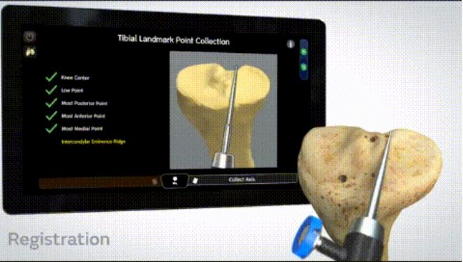
Figure 5: Registration Process taking place on the Commercial Systems, which will look similar to ours.
Dynamic compensation is the task of adapting the planned trajectory based on any motion of the patient and consequently the pelvis from its initial position. During total hip replacement surgery, the forces acting on the patient while reaming are high, causing the patient to move. This moving of the patient leads to inaccuracies while reaming based on the surgical plan. To tackle this problem, our autonomous solution would be constantly checking for any movement of the patient above a certain threshold and would send a flag to the Watchdog Module if that threshold were to be crossed. This threshold would be calculated based on the maximum allowable error as defined by the performance requirements. The flow of decisions for dynamic compensation is seen in Figure 6.
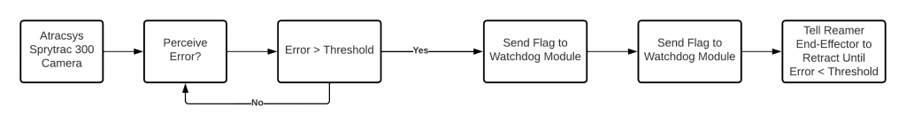
Figure 6: Dynamic Compensation process flow
Control & Actuation
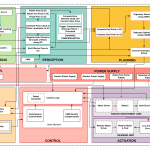
The Control subsystem of the ARTHuR system will be determined by several different inputs. At the highest level, the Control subsystem is controlled by the state machine set by the Surgeon I/O and Watchdog Module. As shown in the Cyberphysical Architecture, the Surgeon I/O has the FMM (Free Motion Mode) button, which switches the state of the state machine between Autonomous Control Mode or Free Motion Mode (FMM). The state of the state machine determines what inputs the control loop takes. When the state machine is in Autonomous Control Mode, the control loop will take inputs from the perception system, getting the frame of the acetabulum, the arm’s end-effector, and the Sprytrack Camera, allowing for the end-effector to track the acetabulum while aligning the end-effector markers to the camera using a Task Prioritization Framework to execute multiple tasks at once. In addition, it will also be avoiding joint limits and singularities. On a lower level, these tasks will be translated to joint velocity commands to the Kinova API. Running these tasks at high frequency will allow for dynamic compensation for any movement of the acetabulum during the operation. A high-level control block diagram on the acetabular alignment task is shown in the figure below. The end-effector control will be isolated, using a hybrid position-admittance control to control the force applied using current sensors or load cells while also having high positioning accuracy. When the perception system detects an error above an error threshold, the reamer will retract and wait until the arm is properly aligned again to begin reaming again.
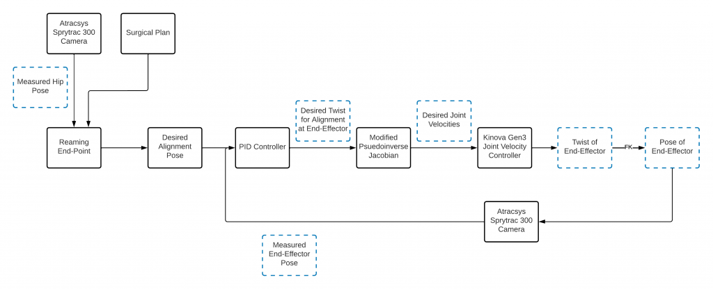
Figure 11: Acetabular Alignment Task Control Block Diagram
When the state machine is in Free Motion Mode, the control loop will not receive inputs from the planned trajectory, and will instead receive feedback only through the joint encoders from the robotic arm. Based on the joint angles, desired torques will be calculated, informing the desired currents that the motor drivers will send to the joint motors. In this mode, the surgeon will be able to set the initial position of the robot arm, greatly reducing the complexity of trajectory planning because the robot arm will not have to plan from moving outside the body to the acetabulum, satisfying the requirement. M.F.6. Furthermore, in this mode, the robot arm will stay in place unless the surgeon moves it by hand. A flow diagram of the Free Motion Mode is shown in Figure 9.
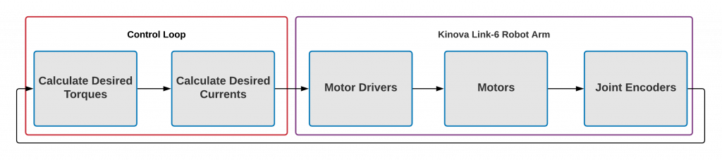
Figure 9: Free Motion Mode Flow Diagram
The Actuation subsystem will contain two discrete units: the Kinova Gen 3 (7-DOF) Robotic Arm and the Reaming Unit (Figure 1). The reaming unit and marker mounts will be attached to the end-effector of the arm mechanically and will be the tool cutting the acetabulum. This reaming unit will utilize a linearly actuated design and will be capable of maintaining the rpm and axial force necessary to cut into the cortical bone in the acetabulum. This system will be controlled via an Arduino microcontroller which will take commands from ROS and run a control loop that monitors the rpm of the motors via encoder feedback, and the axial force applied via current monitoring.
The Watch Dog module within the Control subsystem is a module that checks the system for malfunctions and errors, and reports them to the Surgeon I/O module, satisfying requirement M.N.1. In addition, in case of error, the watchdog module will inform the control loop to react accordingly based on the error. In case the Watch Dog module fails to detect a system failure, the surgeon will have an E-Stop available to them to cut power to the arm at any time.
Watchdog Module
The watchdog module by definition is used to detect malfunctions within the system and react accordingly based on the scale of the malfunction. In our system, the subsystems that are active in nature and need to be monitored are the controls and hardware subsystems. Along with these subsystems, the perception subsystem is monitored because all the other subsystems depend on it.
The watchdog module will act as a health monitoring system and a filter for the flow of information between the subsystems. As soon as the robot arm and the Atracsys camera are turned on, it would check for all critical functions of these subsystems such as communication with the camera and the robot, the frequency at which it is receiving information from the camera, etc. Once the watchdog has determined that the health of the camera and robot is good, it would enable the controller to begin its alignment task. While the controller is aligning, the watchdog will monitor if the robot is close to singularity or joint limits. Once the alignment task is complete and all other subsystem health status is good, the watchdog would enable the hardware subsystem i.e. the end-effector linear actuator to start the reaming process. During this process, the watchdog will monitor reamer speed and reaming progress. All critical information that the watchdog subsystem would keep track of would also be displayed on the UI for the surgeon to monitor and stop the procedure if necessary.
User Interface (Surgeon I/O)
The User Interface (UI, previously called Surgeon I/O) displays important system health information and performance metrics. It allows surgeons to generate a surgical plan for the reaming operation. This means that it integrates with every other subsystem in some capacity. The UI is capable of displaying real-time information being published by the watchdog and controls subsystems. Further, it is capable of rendering and manipulating multiple point clouds through an interactive toolbox. This allows surgeons to visualize the cup implant alignment process and plan the position and orientation of reaming. Finally, once the surgery is planned, the UI is able to communicate this plan to the Controls subsystem. The figure below shows the implant alignment process.
Figure 10: Surgeon UI Cup Placement & Visualization
References
[1] IZI-medical disposable passive blunt probe.”Available athttps://izimed.com/products/disposable-passive-blunt-probe.
[2] “Sprytrack 300 product specifcations.” Available at https://www.atracsys-measurement.com/products/sprytrack-180/.
[3] “CORI surgical system.” Available at https://www.smith-nephew.com/professional/products/robotics/cori-surgical-system/.
[4] T. Haidegger, B. Benyo, L. Kovacs, and Z. Benyo, “Force sensing and force control for surgical robots,” IFAC Proceedings Volumes, vol. 42, no. 12, pp. 401–406, 2009. 7th IFAC Symposium on Modelling and Control in Biomedical Systems.
Spring 2022 Design Archive (Deprecated)
The following sections are outdated and are no longer part of the system due to changing requirements for the system.
Motion Planning
The start and end points of reaming are computed based on the surgeon input and the surgical plan respectively. Using this, the reaming trajectory to be followed is generated using the Pilz Industrial Motion Planner. The optimized trajectory is then used as input to the IKFast inverse kinematics plugin which returns the desired joint angles for the joint to execute at every time step. If a compensation interrupt is triggered from the perception block, the end point of reaming is recomputed to compensate for the motion of the pelvis during surgery.
Control & Actuation
The Control subsystem of the ARTHuR system will be determined by several different inputs. At the highest level, the Control subsystem is the controlled by the state machine set by the Surgeon I/O. As shown in the Cyberphysical Architecture, the Surgeon I/O has the FMM (Free Motion Mode) button, which switches the state of the state machine between Autonomous Control Mode or Free Motion Mode (FMM). The state of the state machine determines what inputs the control loop takes.
When the state machine is in Autonomous Control Mode, the control loop will take inputs from the planned trajectory in the form of desired joint angles. The control loop will then use a hybrid position- and force-based Model Predictive Control (MPC) to move the arm along the desired trajectory. The Optimal Control Problem for the MPC is shown in Figure 7 and a high-level block diagram of our controls is in Figure 8. This use of the MPC will allow the actuation subsystem to have adjustable feed rate to avoid high forces on the acetabulum to limit the risk of fractures, and to satisfy requirement M.N.1 to produce low enough forces be safe around humans, while also limiting the pose error of the end-effector. Previous surgical robotic systems have used hybrid position- and force-based control for the aforementioned reasons [4]. The control loop will then receive positional, velocity, and torque feedback from the joint encoders and torque sensors of the robotic arm.
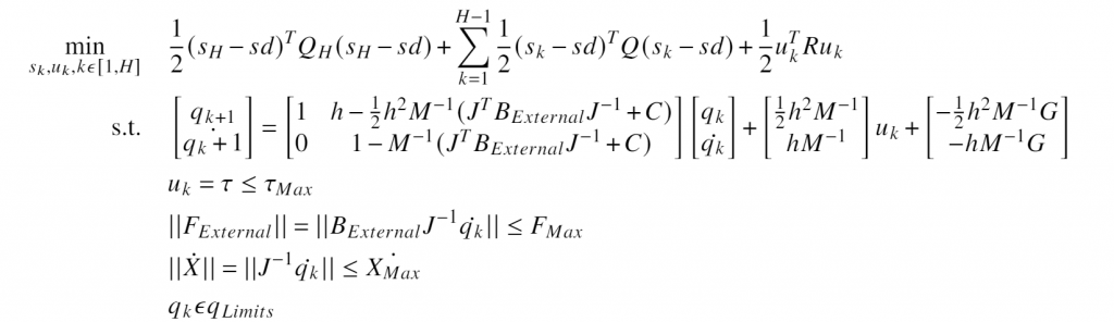
Figure 7: Optimal Control Problem Within Model Predictive Controller
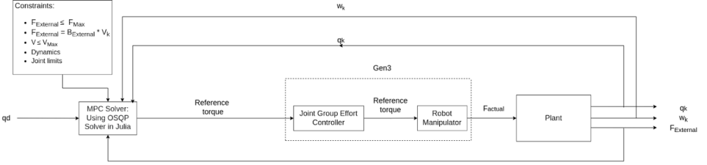
Figure 8: High-Level Block Diagram of Our Controller
 Previous Post