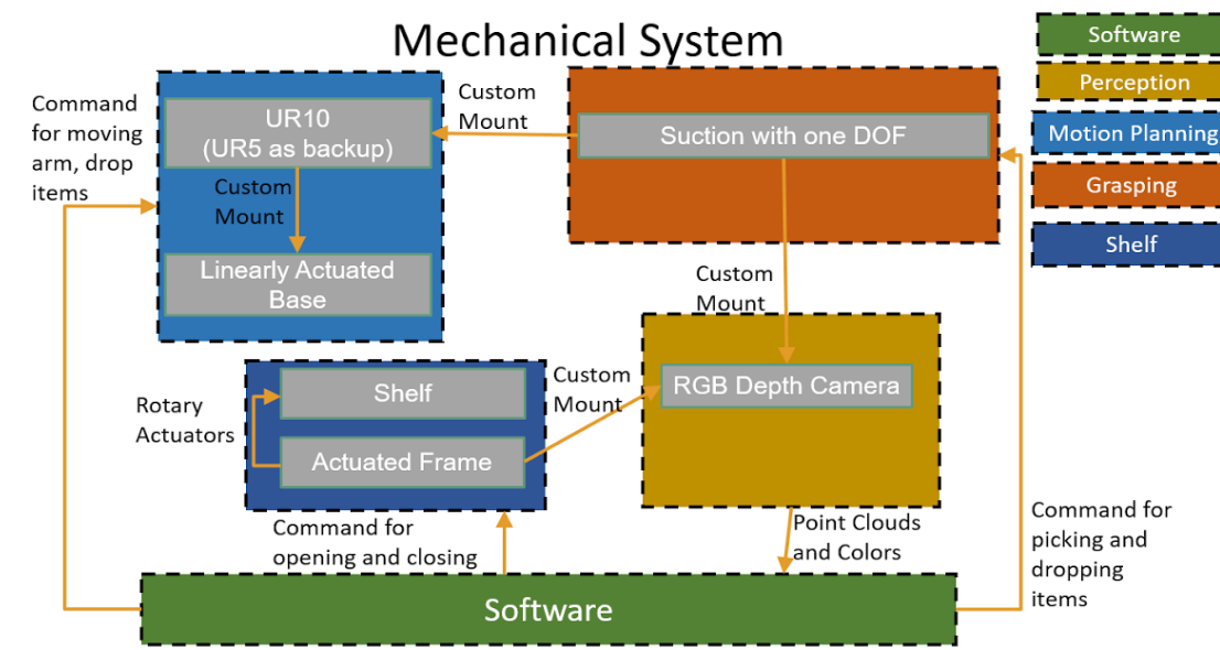
Mechanical System
The cyberphysical architecture has five main sections, software, perception, motion planning, grasping and the shelf.
If enough funding is available, we intend to construct an actuated frame that can fold and unfold the shelf with rotary actuators that would receive commands from the software system of the robot. Excluding the shelf, hardware for this architecture has been broken into three main subsystems that correspond to the systems seen in software. The software system is shown in green and will be explored in more detail later.
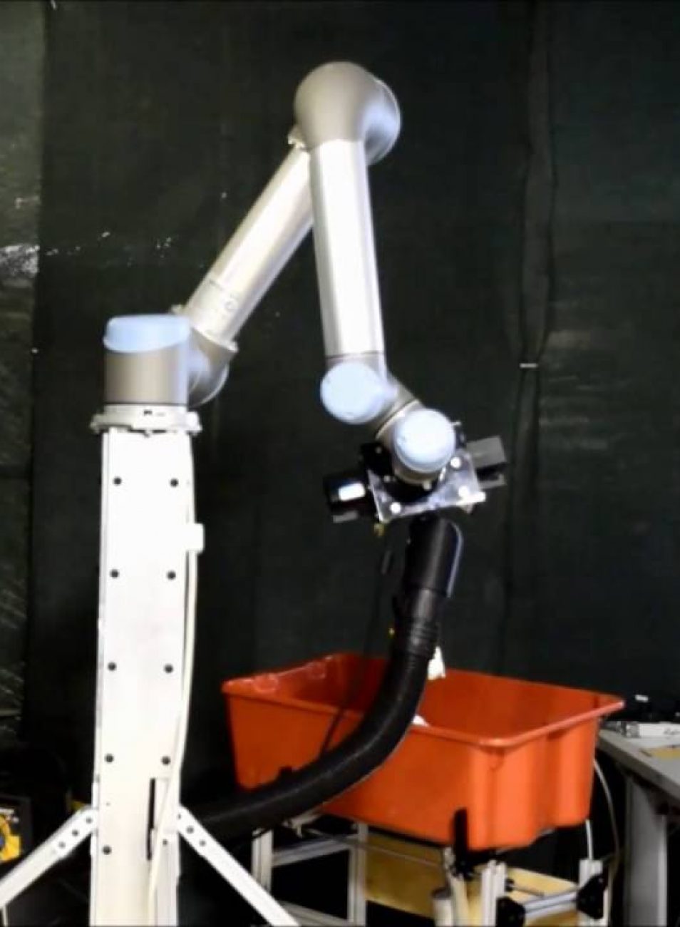
The section in light blue is the hardware that is relevant to motion planning, which includes the UR10 robotic arm as well as the linearly actuated base on which the arm will be mounted. The software system will be able to issue commands to the arm and base.
In red, the grasping subsystem includes a custom made end effector with one degree of freedom on the tip of the suction head. The software system will be able to issue commands to engage suction as well as receive pressure feedback from the suction head.
The yellow section is the perception hardware, which will be four RGB-D cameras. Three of the cameras will be mounted on the shelf frame, and one will be mounted on the end effector. The cameras will be sending a stream of point clouds and color data to the software system.
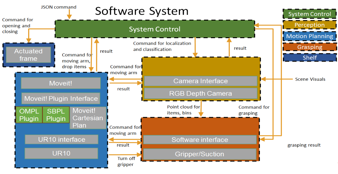
Software System
The following figure shows the software portion in detail. Each dashed box represents a subsystem and corresponding rosnode. Also, all subsystems are capable of communicating with each other through rosservice, which makes communication interfaces unified and easy to maintain.
The state machine and central control is the section in green. High-level flow control and exception handling is implemented in this block. Well-designed system control guarantees robustness and performance.
The motion planning service is represented in the light blue boxes. This subsystem can be used as a service by other subsystems. The Moveit ROS package and SBPL planner are also used to facilitate the development of planning.
The perception subsystem is represented in yellow. The Kinect_bridge is used to connect the kinect driver and the ROS environment. PCL 1.7 is used to manipulate point cloud data.
The grasping subsystem is represented in orange. This subsystem subscribes to the pressure sensor reading and sends commands to control suction power over rosserial. It is also responsible for deciding on grasping surfaces and grasping strategies.
The shelf subsystem is represented by dark blue sections. The system control subsystem can operate rotary motors to fold or unfold the shelf. The planning scene in simulation will also reflect the change in real world.