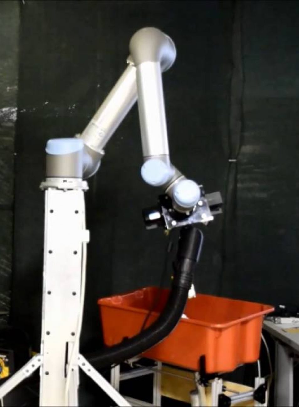
The source of power will be the wall outlet. The robot is stationary and built for a warehouse environment, so this is a realistic power supply. This means that high efficiency is not a concern for our project. The systems that will be using 120AC wall power are as follows:
- UR5 Arm Desktop Computer
- 2 Kinect Sensors
- 1 Vacuum (with relay)
- AC Relay (controlled by Arduino)
- Actuated Base Controller
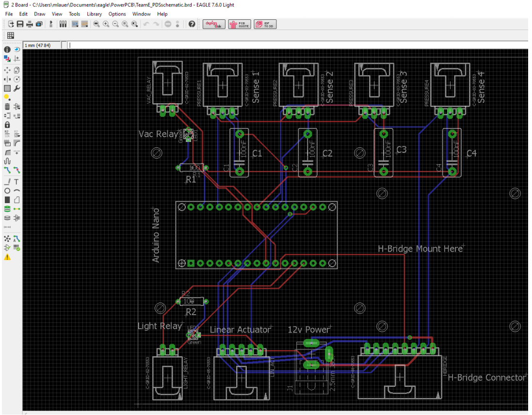
The systems that will be powered by our custom board are as follows:
- Linear Actuator:
12V nom 200ma nom 650ma Stall Current Arduino Uno: 7-12V nom 500ma Max Input Linear Actuator: This system will need some regulation and an H-bridge to reverse the direction of the motor. We will require one connector with 5 pins. 2 of the pins are for power and gnd and will need to carry at least 650ma (Stall). The other three pins are wired to an internal potentiometer on the motor and will not require any special protection or high current. We have an H-bridge kit that we will use to control this motor. The H-bridge has internal diodes to prevent reverse voltage damage. We will also use a 1 amp fuse to prevent catastrophic shorts. The Hbridge receive a regulated 12V signal from a wall wart DC power supply. The H-bridge takes a logic voltage of 5V which can be supplied from the Arduino (the Arduino’s output is regulated and current limited below the max input for the H-Bridge) We have already attached LED’s to the H-bridge that show the direction of the motor and whether the H-bridge is drawing motor power.
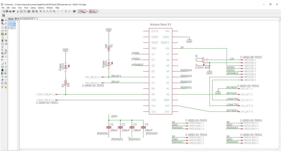
- Arduino Uno:
For power on the Arduino we will plug into our computer. The Arduino and USB port already have regulation and we do not plan to implement additional regulation. For connectors, the Arduino will need four pints to communicate with the H-Bridge (currently on a separate board), 3 pins to get feedback from the potentiometer on the linear actuator, and two pins for the AC relay. Each of these pin sets will have its own connector. These are not power supply connections or anything that would require serious regulation. We plan to leave these connections unregulated. The remaining systems are all able to plug into the wall, so we will not include their power supply system in the PCB