SVD System Performance
SLAM Subsystem
| Mandatory | Mandatory | Mandatory |
| M.F.R.2 | Simultaneously Map and Localize the Environment | Relative pose error(T) <= 15cm Relative pose error(R) <= 10 deg |
During the Spring Validation Demonstrations, our system successfully met the performance requirements for the Simultaneous Localization and Mapping (SLAM) subsystem. The testing environment was provided by the Outersense team, and we evaluated the SLAM performance using their layout. Both rotational and translational errors were assessed by comparing the system’s performance to the available ground truth data.
The translational error remained below the threshold of 50 millimeters. However, we observed that the rotational error exhibited occasional overshoots when executing turns. Upon further investigation, we discovered that the ground truth data we were using for comparison was not entirely accurate, as it was not obtained using high-precision equipment such as a total station.
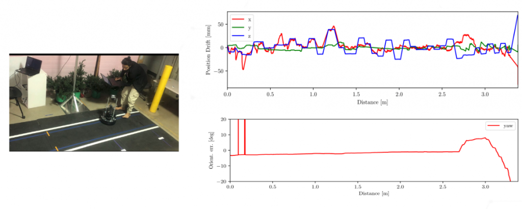
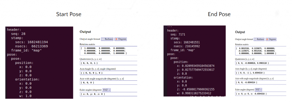
To obtain a more reliable evaluation of the rotational error, we conducted a loop closure test. The results revealed that our system demonstrated an error of approximately 6 degrees, as depicted in the corresponding figure. In light of these findings, we have determined that a different approach is necessary for accurately measuring the SLAM metrics during the Fall Validation Demonstration.
For the upcoming demonstration, we plan to employ a more precise method for determining ground truth data, which will enable a more accurate assessment of our system’s performance in relation to the SLAM metrics. By implementing this enhanced approach, we hope to further refine the system’s capabilities and ensure the achievement of our performance objectives during the Fall Validation Demonstration.
SLAM – Loop Closure Test
Planning Subsystem
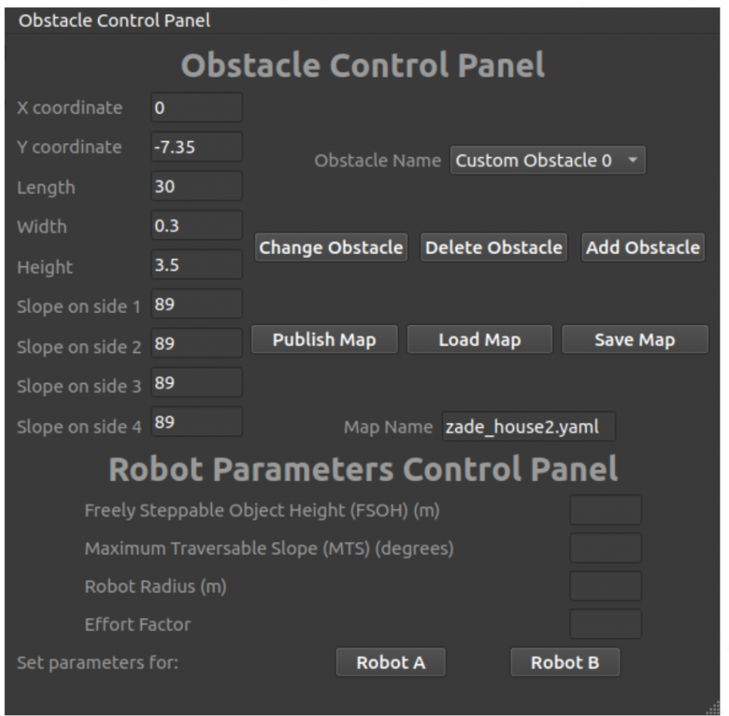
For testing the planner thoroughly, we developed a Qt GUI interface (see below figure) that could allow the tester to add or modify obstacles on a simulated 2.5D grid map. The tester could control the location, dimensions, and slopes on each side of rectangular obstacles.
A total of 7 test cases across 3 layouts were developed, to thoroughly test each aspect of the planner. Each had walls and obstacles of varying positions, locations, and dimensions. In each case, the planner was run and the path generated was visually verified.
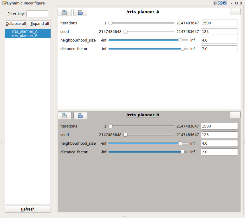
The Qt GUI interface could also change all 4 robot parameters for two robots. This allowed the tester to see the changes in path when the robot parameters change. Additionally, we also developed a RQT GUI plugin interface (see Figure 17b) that controlled planner parameters such as the number of iterations, the random seed, the neighborhood radius, etc. and allowed changing the start and goal location as well.
In below table, the results are shown for different test cases upon which the planner was initially developed. These test cases allowed for the implementation to include edge cases where the planner could potentially fail, and apply mitigation strategies (such as running the planner for longer iterations). Lastly, the unit tests served the purposed of debugging minor issues in the planner that were not easily detected during implementation and in overall subsystem tests.
| Test Case/Layout No. | Summary | Result |
| 0 | Finding a feasible path | Success |
| 1 | Finding an optimal path | Success |
| 2 | Effect of FSOH on optimal path | Success |
| 3 | Effect of MTS on optimal path | Success |
| 4 | Effect of Gradient Influence on optimal path | Success |
| 5 | Effect of Robot Radius on optimal path | Success |
| 6 | Effect of Robot Radius, FSOH and MTS | Success |
| 7 | Feasible/Optimal path in a difficult layout | Success but only with high number of iterations |
For analysis, we included an option for verbose output in the planner to get the details of each step the planning algorithm was taking. Additionally, the planner also outputs the total time taken as well as the cost of the generated plan for analysis (see Figure 18). In our analysis, we found that the planner starts slowing down significantly if the number of iterations go over 2000. However, keeping the iterations below 1200 gave a lot of sub-optimal paths. Hence we decided the number of iterations to be 1500. We also tested the effect of neighborhood size, and the results were similar to the number of iterations; very slow planning for higher neighborhood sizes and sub-optimal results in case of low neighborhood sizes. The sweet spot in this case was 4.0 meters.