G.H.A.R. Software Stack Cyber-Physical
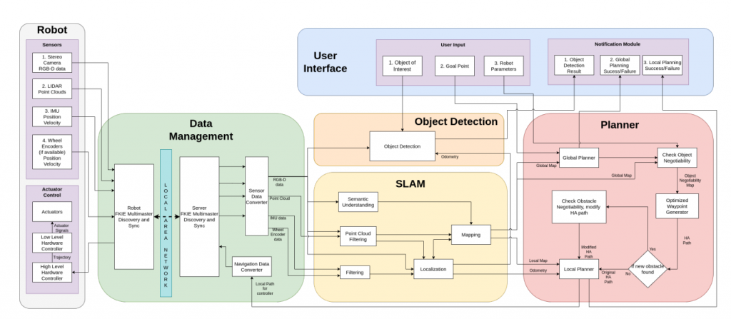
As seen in the figure above (details the full Cyberphysical architecture of the system) the Cyberphysical architecture consists of 6 modules: Robot, Data Management, SLAM, Object Detection, Planner, and User Interface. Each module has been expanded upon in further detail in the
following sections.
Robot
This module mainly consists of the robot hardware, the sensors (stereo camera, IMU, LiDAR and wheel encoders if present), and the actuators (the motors controlling the wheels of a wheeled robot or the joints of a legged robot). The low level software is also included, this software interacts with the sensors and actuators, like the control software that is responsible
for converting the local path generated by the planner into a robot trajectory and subsequently into actuator signals
Data Management
This module contains all the necessary blocks for the off board computer to interact with the onboard computer of the robot, as well as blocks that enable the high level planning software to interact with any robot. The multimaster sync and update blocks are crucial to the system operation.
FKIE Multimaster: The main advantage of using FKIE multimaster is that it allows the selection of ROS topics and services to be broadcast over the network. This reduces the network burden of broadcasting of each and every topic and service running on both the robots. The FKIE multimaster consists of master discovery and sync nodes that run both on the
onboard robot computer, as well as the off board computer and ensures that both ROS masters can discover and sync the selected topics/services between each other. This communication happens via a Local Area Network, such as WiFi. Since different robots employ different sensors and/or control software, it is imperative to convert the message type of these different sensors and control software into a common language that the high level navigation software can understand. The Sensor Data Converter block
converts the output of all the robot sensors to an interpretable message type for the navigation software. Similarly, the Navigation Data Converter block converts the output of the navigation software (the local path) into a format that is interpretable by the robot control software.
SLAM
The blocks in this module carry out the simultaneous localization and mapping for the robot. The blocks here receive the sensor inputs, filter them, and then use the filtered data to simultaneously localize as well as map the environment. Additionally, since semantic SLAM is being used, a scene understanding block is necessary to perform semantic segmentation on the image data, to extract information about the scene. This subsystem sends the robot pose to the planning subsystem.
Object Detection
Once the goal point is reached, the object detection module is used to detect the object of interest requested by the user. This is a simple subsystem whose job is to detect the object of interest. It takes the camera feed, the odometry and the user-specified object of interest, and tries to detect it in the environment. If the object is detected in the camera feed,
the module informs the user and also provides the pose of the object detected. A simple neural network will be used to detect a limited set of objects and put bounding boxes on it, which will then be used to calculate the pose of the object.
Planner
The planner is responsible for charting the path for the robot. It is required of the planner to deal with robots utilizing different types of locomotion strategies, without compromising the robot’s abilities to navigate the environment. To do this, the planner needs to take into account object negotiability (objects that the robot can traverse) to plan a suitable path. This is done via additional blocks within the planning module that check for object negotiability, which is used to generate an object negotiability map. This is then used by the planner modules to generate a hardware agnostic path.
Part 1: The planner subsystem takes as input the robot odometry (from the SLAM subsystem), the global and local maps, the goal point given by the user, and most importantly, the robot parameters. First, the global planner generates a global path using the global map, without taking into account robot specific capabilities and only considering very large obstacles (i.e. walls). Then, the check object negotiability module uses the robot parameters and global map to classify the rest of the obstacles in the global path as either non-negotiable (if the robot has to go around it) or negotiable (if the robot can go over or under it).
Part 2: The global path and the object negotiability map is used by the Optimized Path Generator to
modify the global path. This will generate a hardware agnostic path that utilizes the abilities of the robot to traverse traversable obstacles. As the robot moves along the path, it might discover new obstacles. If it discovers new obstacles, once again a check for the negotiability of the new obstacle is performed and the hardware agnostic path is modified accordingly. If no new obstacles are found, the robot continues following the old hardware agnostic path. Finally, the local planner takes in the hardware agnostic path and the current odometry as input, and generates a local path for the specified robot.
User Interface
The User Interface module allows the user to control the software and receive feedback on whether the robot was successful or not. This subsystem aids the communication between the user and navigation
software. The user gives the software three main inputs, namely, the robot parameters, the goal point, and the object of interest. The software then outputs the object detection result, as well as the planning success or failure, for both local and global planning. The inputs and outputs will
be taken and displayed from a simple command line or RQt interface respectively, that runs on the off board computer.