Flight Control Components
- PixRacer flight controller
- Telemetry antenna
- RC Receiver
- ESCs (6)
- DC Motors (6)
- USB-Telemetry Cable
- Onboard Computer
Platform Power Distribution Components
- 14.8 V 6600mAh 70C LiPo Battery (2)
- Power Distribution Board
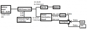
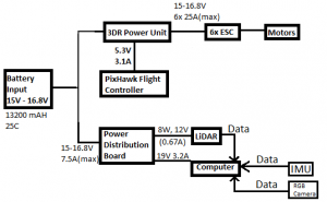
The flight platform is powered off of two 14.8 V LiPo batteries in parallel that connect to a board that distributes power to the PixRacer, Gigabyte Brix, and the LiDAR. For flight, the RC receiver obtains commands from the RC controller at ground level and sends them to the PixRacer. A switch on the RC controller allows to switch control from tele-operation to onboard control for autonomy. The PixRacer sends PWM signals to the Electronic Speed Controllers (ESCs) which control the speed and direction of the six motors, enabling flight. Meanwhile, the telemetry antenna broadcasts messages back to the ground control station sent by the PixRacer.
October 13, 2016
We have achieved maiden RC flight. To do so, we did the following:
- Mount the PixHawk with correct orientation.
- Interface a safety switch, a buzzer, Telemetry radio module, RC control receiver, 3DR GPS+Compass and 3DR power module for battery monitoring.
- Load a microSD card to store firmware.
- Connect motor outputs of PixHawk to the ESC inputs.
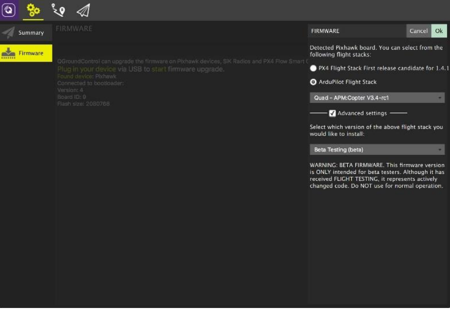
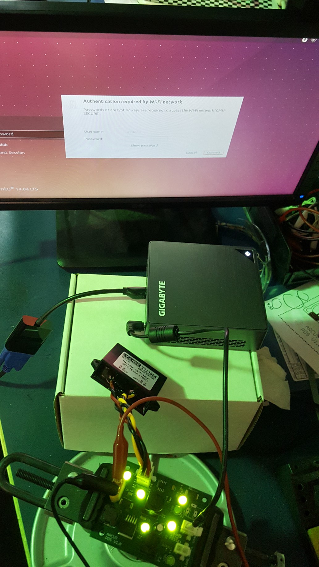
- Connect the PixHawk and install appropriate firmware using QGroundControl
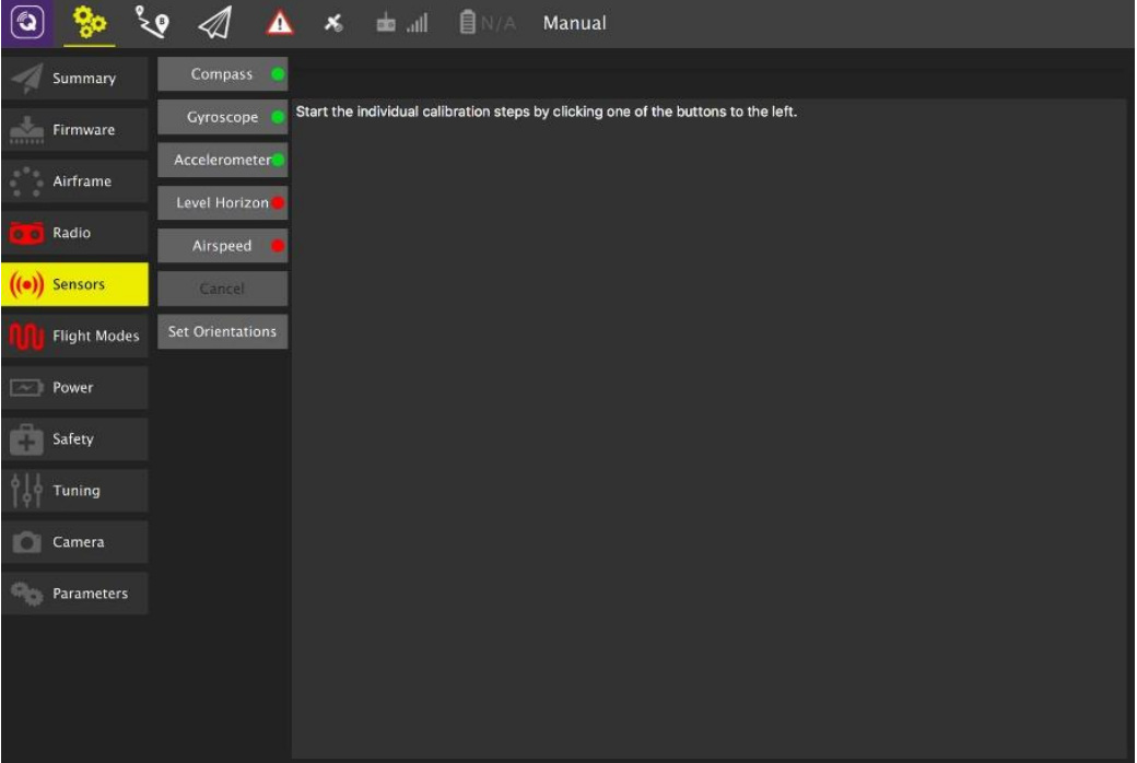
- Calibrate sensors and RC control using QGroundControl.
- Mount batteries and verify RC control.
- Maiden flight.https://youtu.be/kITs1Y4I7oQ
November 18, 2016
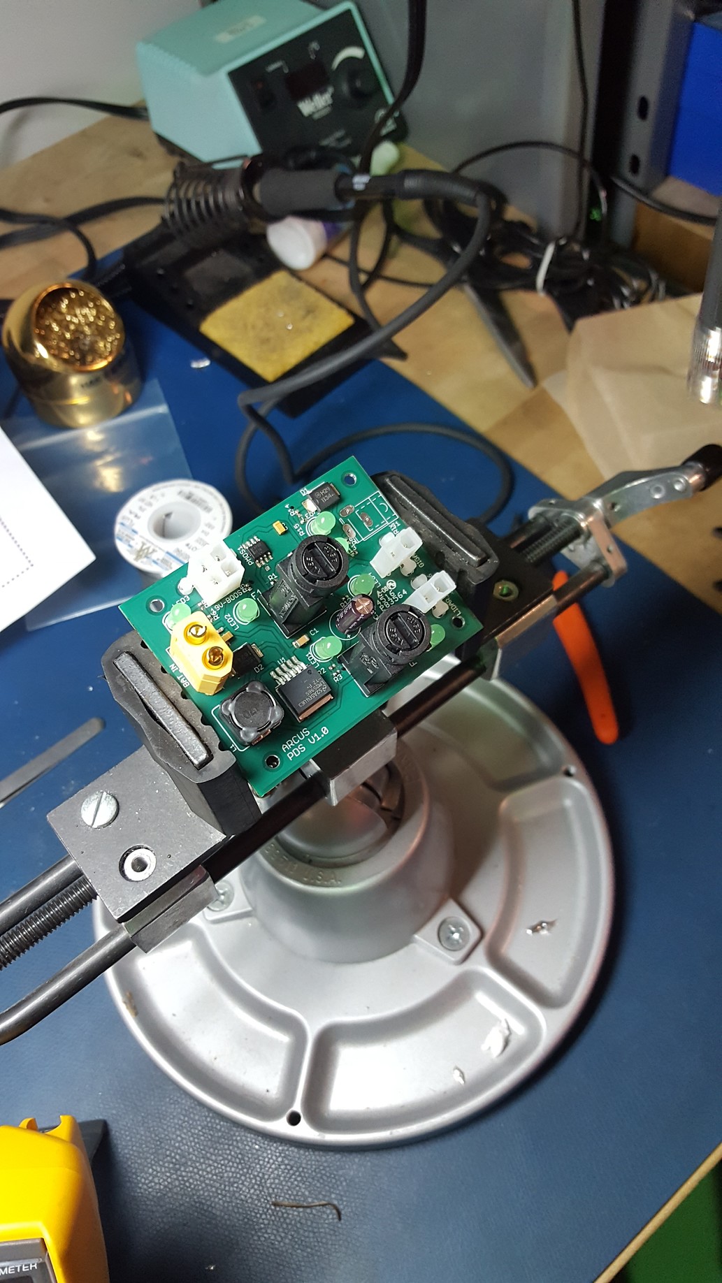
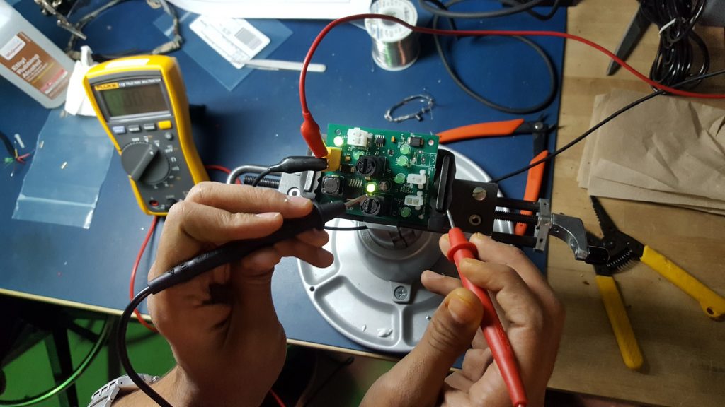
Since receiving the PCB and electrical components for the power distribution board, we have cleaned, soldered components to, and done basic continuity, resistance, and intermediate and final power checks. Overall, we found only a couple minor problems: the LED for the Velodyne does not light up, likely due to an improperly soldered resistor, and we wrongly sized the holes for the DC power jack, so we will need to design a workaround for that. Finally, we are reading in slightly lower input voltages than expected for the Brix and Velodyne at 11.95 V and 18.85 V but this has proven to not be an issue. Overall, the PDB works as expected, and we were able to power on the Gigabyte Brix successfully.
February 1, 2016
The electrical system was revised to mitigate an issue where the onboard computer would power off when the motors collided with an obstacle. In such a circumstance, the 3DR Power unit shuts off power to the motors, and consequently the PDB in the old electrical design.
Furthermore, the PixRacer was integrated with the on-board computer using MAVROS and a custom TELEM2-USB UART adapter cable. Details of the adapter can be found in mjnaik_ILR07
February 15, 2016
MAVLink and MAVROS integration finished with a mode-switch assigned to the RC controller for switching between tele-operation and autonomous modes.
https://www.youtube.com/watch?v=V_MwvGUzj2I
March 1, 2016
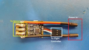
The ESC were switched out. Earlier, we were using T-Motor AIR40 ESCs which have open-loop PWM control like most ESCs. Hence, in case the battery voltage drops, there would be no compensation in PWM to maintain motor RPS. Instead, the ESC32 v3 have closed-loop feedforward voltage-RPM control. These are the new ESCs currently mounted on the drone.
We also switched the firmware to the custom Robust Adaptive Systems Lab firmware which takes into account motor-torque and response characteristics for better control.
March 22, 2016
The new flight control firmware was tuned for stable flight
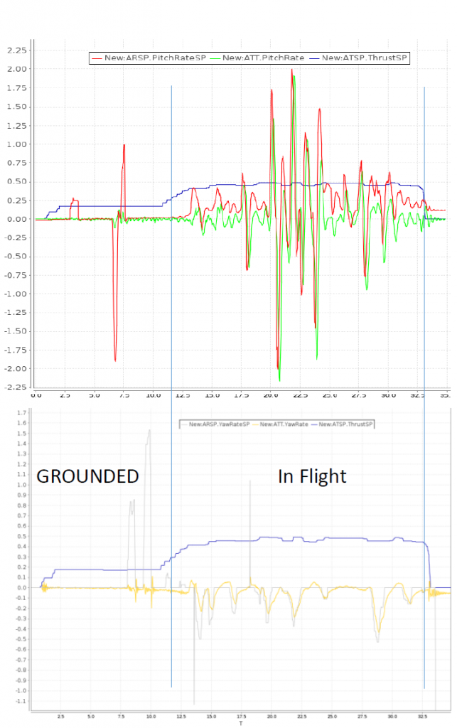
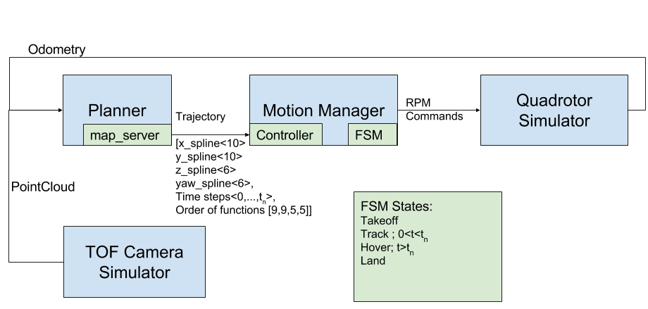
A trajectory following and motion management framework started being tested in simulation. The following is the high level architecture of the same
Updated 7 April 2017