April 15, 2017
The modules for logging GPS coordinates from the drone onto a server were implemented. The signature detection relies on accurate GPS from the drone along with timestamps for those readings. These readings along with the timestamps are aligned with the timestamps of the image frames from the camera to precisely pinpoint the location and orientation of the camera when the image was taken, and then extrapolate the exact GPS location of the signature from this information.
March 15, 2017
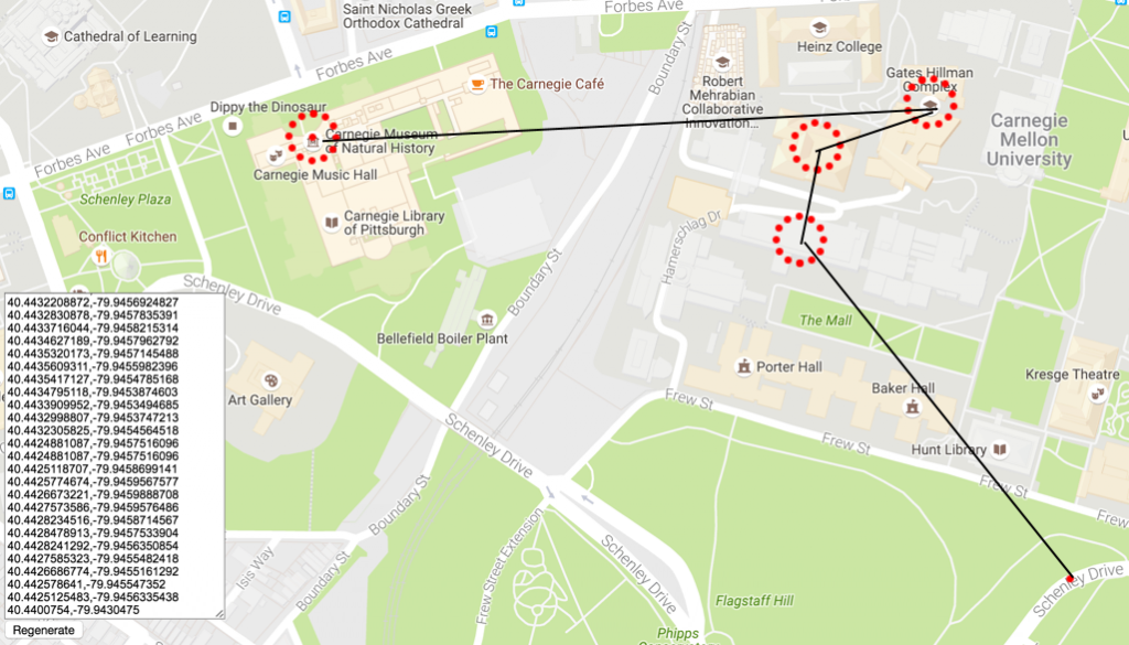
When NREC was chosen as the final the flight plan had to be changed due to lack of space. The current plan is to do a sweep of the area instead of picking regions of interest. The signatures would be place along the field and the sweep pattern would be decided such that it the drone would be able to achieve maximum coverage of the area. The sweep pattern is shown below.
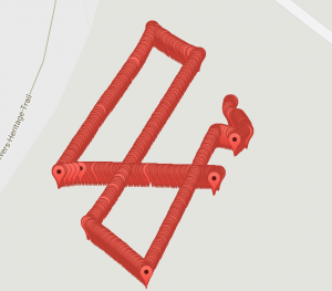
Sweep pattern at test site
Waypoint Navigation Test:
Dec 8, 2016
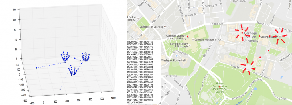
GPS Accuracy validation
For validating the GPS accuracy of the flight system, GPS from the two different sources were compared against each other. The GPS locations from the Drone’s inbuilt GPS was compared and tallied with the GPS coordinates as reported by the smartphone.
To measure the randomness in the GPS data reported by the phone and the drone, the following experiment was done:
- Place the drone and phone at the same location
- Log 25 GPS readings from the drone and phone spread out over a few minutes
- Compute Standard deviation for the values
In addition, to understand any random errors within individual GPS sources, experiments were done to record GPS coordinates reported by each device for a given location and the standard deviations of the readings were noted. The table below shows Latitude values reported by the drone and the phone, and a comparison between them.
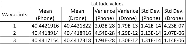
The two sources were found to be fairly accurate in terms of exhibiting any random errors. The one thing that was not tested extensively was the possibility of any static bias in the two sources. Though this is addressed to some extent by comparing and tallying the sources with each other, a more comprehensive test will help understand and address any static bias the systems might have.
Nov 22, 2016
Waypoint Navigation
- Used third party platform code to develop an app to input GPS waypoints
- Utilized DJI Mobile SDK to enable interaction between the app on phone and the flight controller on the drone
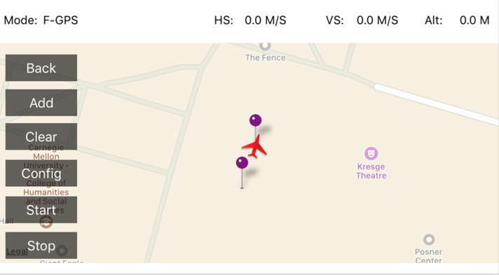
Successfully tested waypoint navigation in the field. You find a video of the test flight here.
Following is a screenshot of the app:
Nov 10, 2016
Matrice 100 Setup
Assembly:
- Structural frame
- GPS module
- Battery compartment
- Propeller & Propeller guard
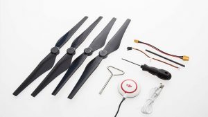 Parts of Matrice 100
Firmware Upgrade:
- Upgraded remote controller(through DJI Go)
- Upgraded Matrice 100(through DJI Assistant2)
Calibration:
- Tested rotation of motors(through DJI Assistant2)
- Calibrated the compass(through DJI Go)
- Calibrated the remote controller(through DJI Go)
Waypoint Generation
Implemented waypoint generation version 2.0 with spiral local search pattern.
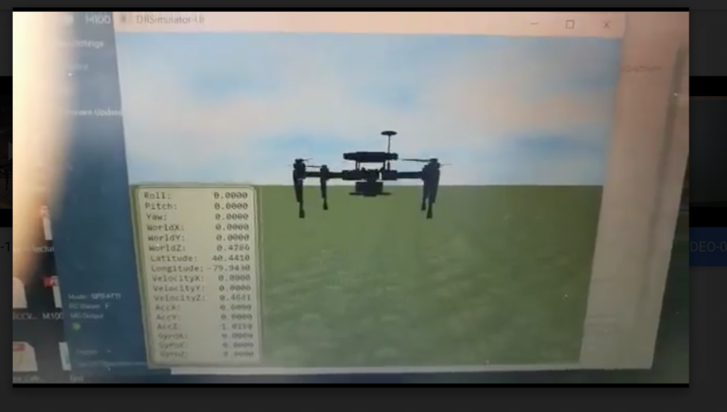
Waypoint Navigation on Simulator
Tested DJI Mobile SDK to enable waypoint navigation on DJI simulator.
Oct 27, 2016
Waypoint Generation
Implemented basic waypoint generation with basic circular local search pattern.
Basic UI for specifying locations of interest/waypoints:
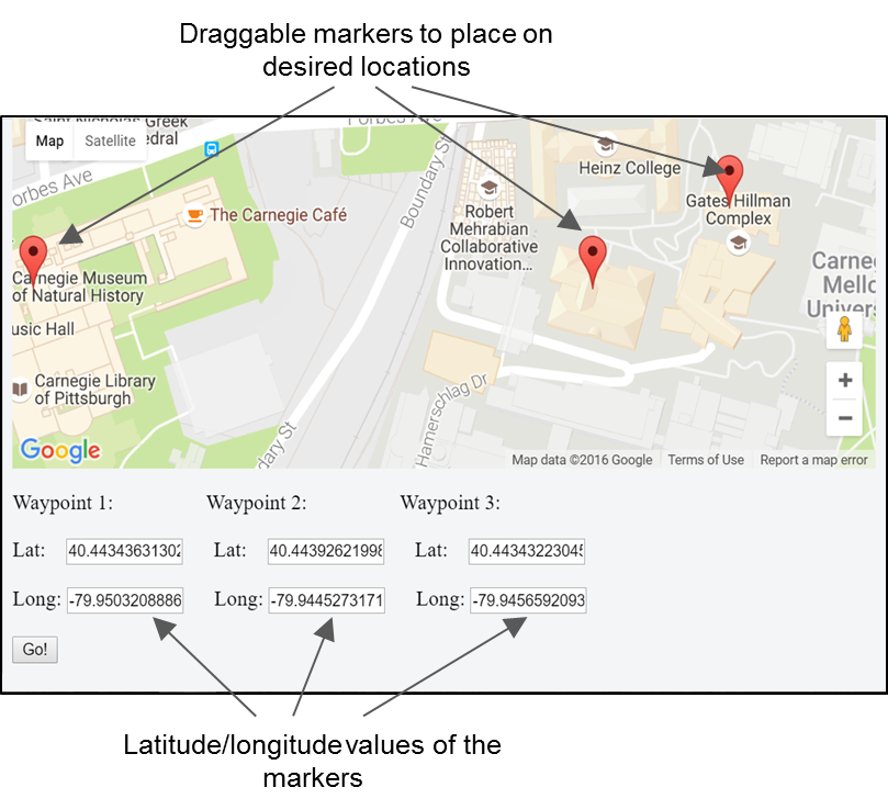
How do I input my locations of interest/waypoints?
- Drag the markers on the map
- Click Go!
How it works?
- Prototype on JSFiddle
- Used Google Maps API to create draggable markers
- Click event on the markers reports lat/long values in the text boxes
Oct 20, 2016
Intermediate Waypoint Generation
Defined an initial strategy for navigating an area of 200m x 200m and conducting local search at the four given waypoints. Following figure depicts the navigation area and search pattern we assumed.
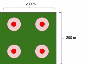
Initial Strategy:
- Reach location of interest at an altitude of 15 m, speed ~5 m/s
- Spiral up to an altitude of 30 m, complete one circle of radius 6 m, speed ~2m/s
- Move to the next location of interest while reducing the altitude to 15 m
How does our initial strategy do?
- 44m diameter circular area covered around each location of interest
- >98% overlap between two frames for both thermal and RGB cameras
- good stitching
- Well detailed imagery
- Ground sampling distance: 0.5 cm/pixel for RGB, 2.7 cm/pixel for thermal