Please note that we are no longer using this power distribution system. Due to simple power requirements of all the components onboard, we are powering them through a mobile power bank.
Dec 25, 2016
Fabrication and Testing
The fabricated power distribution board is shown below:
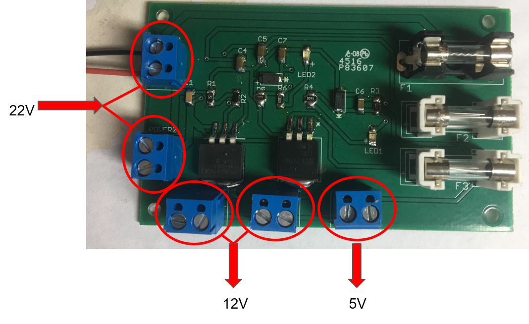 fabricated power distribution board
We connected our PDB with the battery of Matrice 100, and measured the voltage of each output. It turned out that both the 5V output and the 12V output worked perfectly.
Strength and Weakness
The power distribution board we designed have several advantages:
- Is able to protect the circuit from misoperation
- Is compact and lightweight
- Have additional connectors for backup use
However, there is still a weakness. If the battery is fully charged, the output voltage of the battery increases up to 25V, which is quite close to the maximum input voltage of the 5V regulator. In order to mitigate this risk, we need to reduce the input voltage of the regulator by adding a step-down transformer before it. In addition, we can change the type of the regulator so that it has a higher maximum input voltage.
Dec 8, 2016
Manufacturing files
For eventually printing the board, I still need to create manufacturing files from .brd file. The required files for printing are as below:
.drd – drill file
.cmp – top copper layer
.plc – top silkscreen layer
.pls – bottom silkscreen layer
.sol – bottom copper layer
.stc – top soldermask layer
.sts – bottom soldermask layer
After submitting all these files to www.freedfm.com, they could be checked for incoming orders. The multilayer output result is like:
Multilayer output result
Dec 2, 2016
Conceptual Design
The input is from the battery of Matrice 600, whose voltage output is 22.2V. More specifically, the battery model is TB475, and its type is LiPo 65, with 4500mAh capacity.
In terms of the output, our system needs to power an onboard computer for storing data of the sound sensor and communicating with the DJI flight controller, as well as a DC motor to drop the rescue package. For the onboard computer, our idea is to use the ODROID-XU4, whose required voltage is 5V and its rated current is 4A. And as 12V and 3A output is able to drive most 12V DC motors, the subsystem for DC motor is designed in this way.
The protection circuit which can protect against short circuits, overvoltage, and reversed input is required to both subsystems. Also, our system includes 2 status leds to show whether the protected supply for each subsystem is operating.
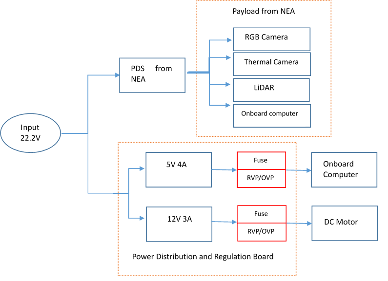
Conceptual Design of PDS
Schematic Design
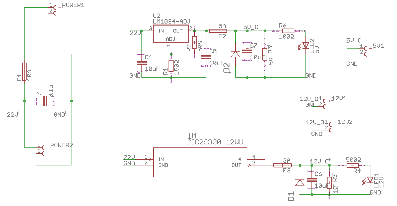
Schematic of PDS
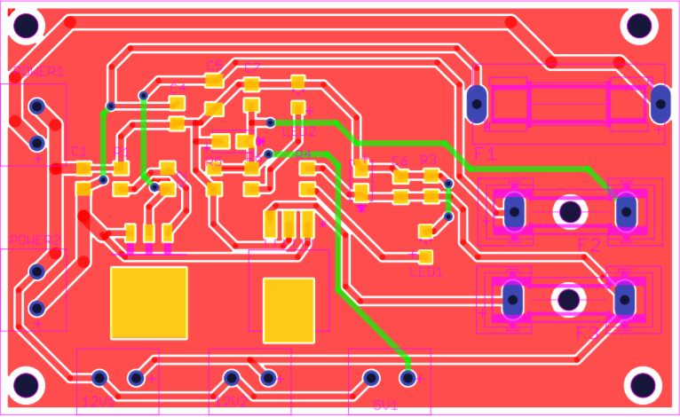
Layout Design
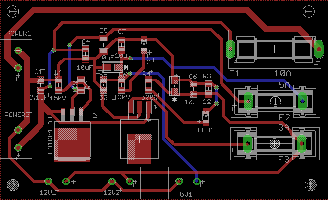
Layout of PDS