1. Visual Structure
2. Hardware
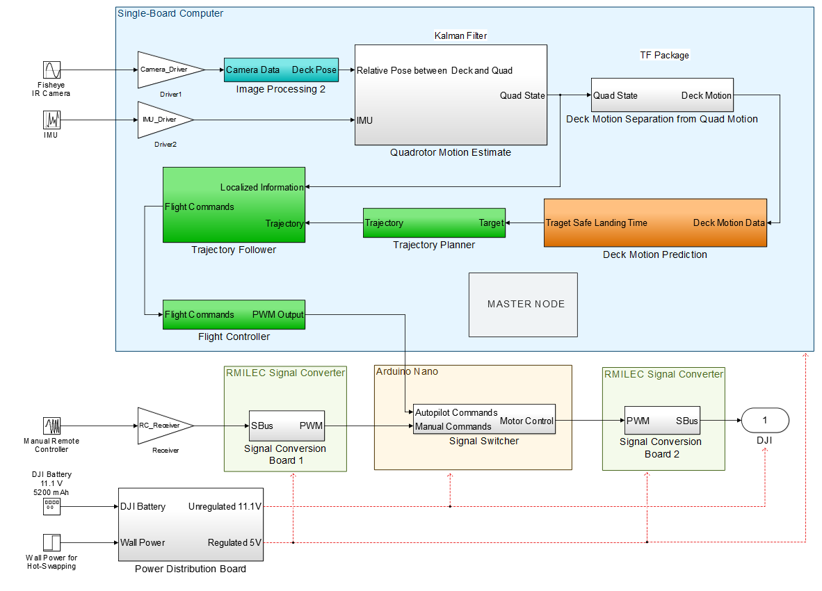
The hardware components of the system are depicted in white blocks in the cyberphysical architecture. The hardware of the system includes the sensors, the single-board computer, and the mobile platform. The overall hardware design is dictated by the chosen vision system. The trade studies show the determination for this vision system setup, and it will provide vision information about the environment to the algorithms on the single-board computer. Additionally, an IMU sensor will supplement the vision information to assist in distinguishing between motions of the deck and motions of the quadcopter.
Our single board computer houses the primary software and processing for our system. The image processing, localization, prediction, trajectory planning, trajectory following, and flight command subsystems all reside here. Additionally, there is a master logic node and master signal routing node that handles switching between states and routing the proper signals.
In addition to our primary single board computer, we have two signal conversion boards and an Arduino Nano mounted on a custom printed circuit board. The signal conversion boards convert the remote control signal from SBus to PWM and the motor controls from PWM to SBus. This is needed because the DJI Phanom II expects SBus communication from the remote controller, but our single board computer and Arduino Nano use PWM communication. The Arduino Nano takes the inputs from the remote controller and the single board computer and determines which signal should be routed to the rotorcraft. The printed circuit board allows for all of these components to work together easily with no need for stray wires. It also allows us to flip a physical switch on the printed circuit board which bypasses the entire Arduino system and lets the quad connect directly to itself. This is useful for troubleshooting if the Arduino is not working.
Our printed power distribution board takes power from the DJI Phantom II’s battery and distributes it to the various other boards. There is a 5V regulator on this board to provide power to the single board computer and the conversion boards. The Arduino Nano has an internal power regulator, so it receives the full voltage of the battery. The cameras and IMU are powered via USB from the single board computer.
3. Software
The on-board computer is the primary decision-making component of the system, and all of our algorithms will be housed on this computer. The software consists of four main algorithm groups: localization, prediction, state estimation, and flight control.