1. Power Distribution Board
Schematics and Layouts can be found here: Drawings, Schematics, and Datasheets
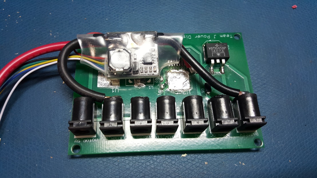
Revision 3:
Revision 2 board with 3DR power module replacing the regulation component, pictured below.
Following initial testing, the power distribution board revision 2 appeared to work as designed. It steps down the 11.1V input from the quadcopter battery to the 5V needed by the Odroid. When observing the output with an oscilloscope however, we noticed that there was some small noisy disturbances on the ground line.
Upon attempting to power the Odroid, once the boot sequence draws more than an amp, the noise in the ground plane becomes amplified significantly. This causes a brownout in the Odroid that prevents the board from booting. Even first booting the board from its standard power supply then hot swapping to the power board only worked for a few seconds.
The root cause of the noise was never determined, so in the interest of time, we decided to use a 3DR power module to perform the same function, albeit in a less clean manner. The extra routing and hot swap feature from our board are still used with the 3DR module providing the regulation component.
Revision 2:
Following the reworks required for the Power Distribution Board Revision 1, we decided to design a new board revision to account for the problems found in the first board.
The new board also has all parts laid out on a single side to allow for better mounting integration into the new sensor harness, and all power jacks facing the same side for easy access and cable routing.
Revision 1:
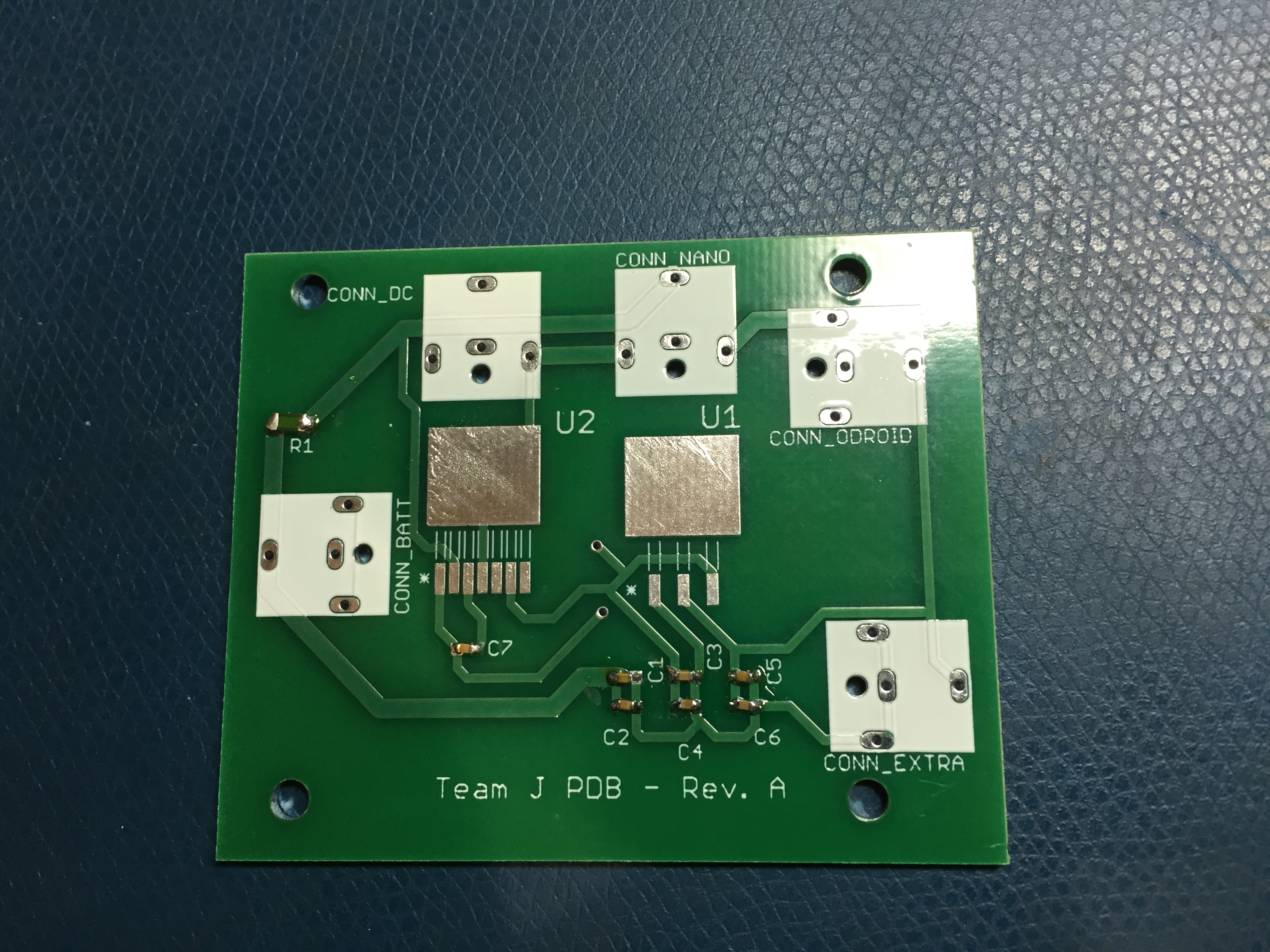
Power Distribution Board, unpopulated
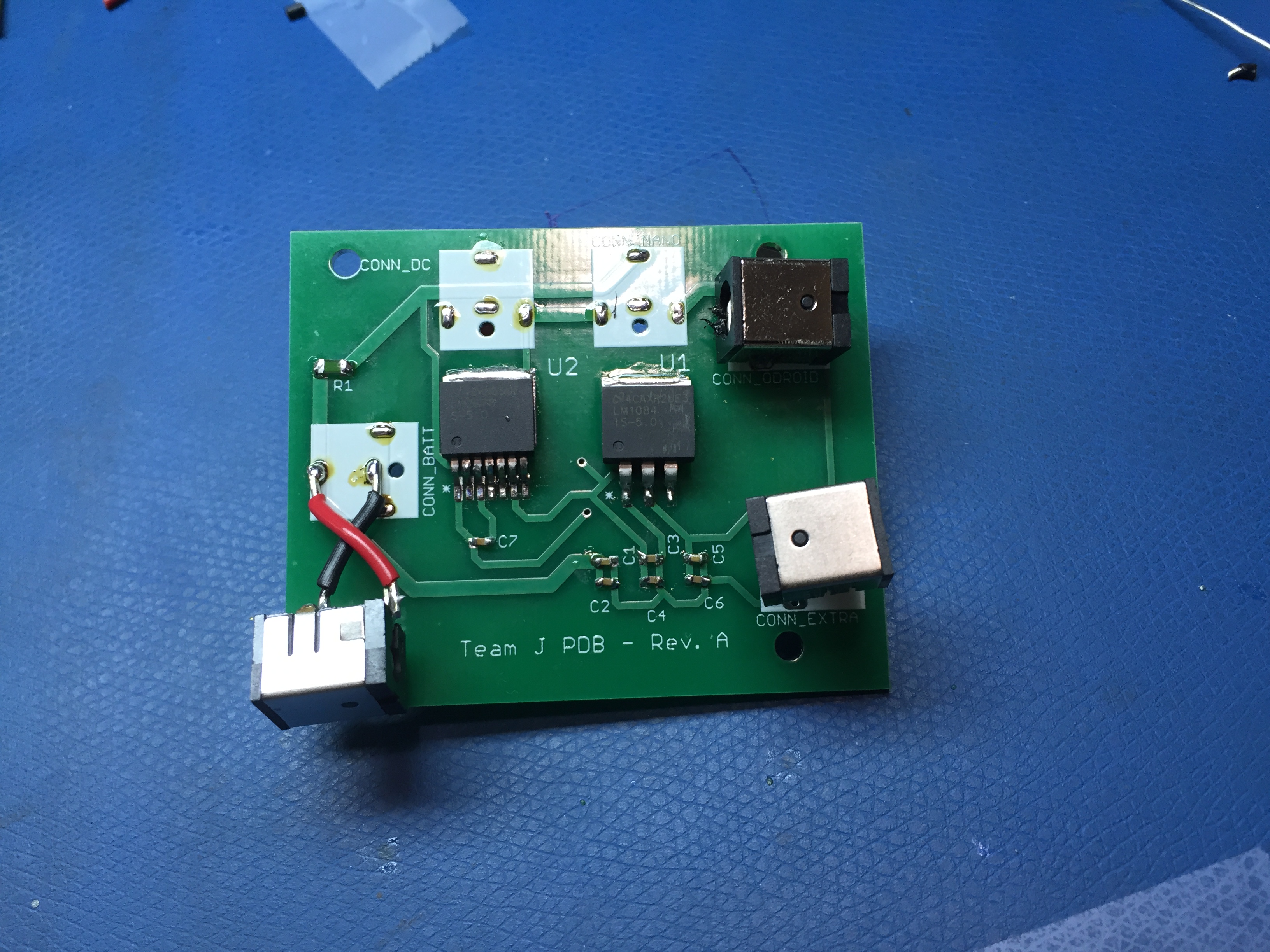
Power Distribution Board, Top Side
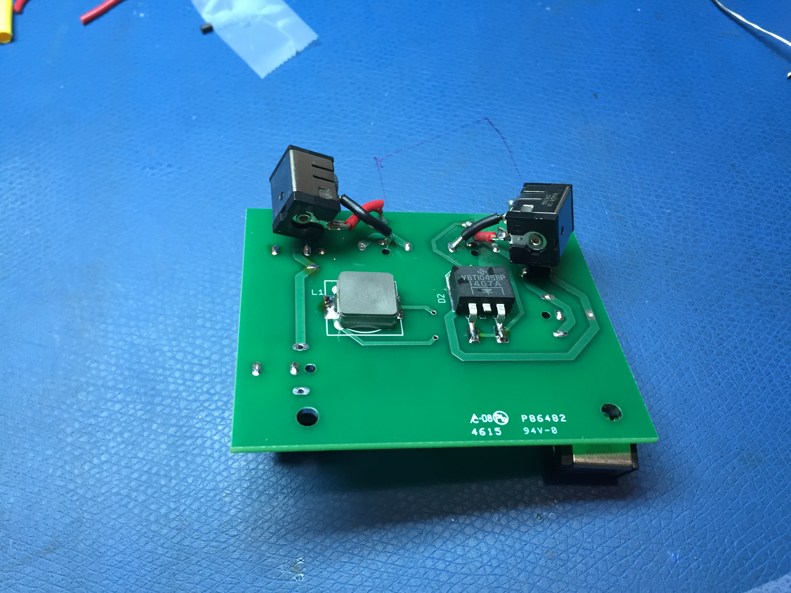
Power Distribution Board, Bottom Side
Rework Notes:
Barrel jack connectors placed backwards in layout, reworked using wires.
Switching regulator output voltage too low, causing LDO to drop out, reworked by bypassing switching regulator.