1. Localization Algorithm
The localization algorithm is broken into three pieces:
- The mapping from the 2D beacon image to the 3D relative pose between the deck and the cameras
- OpenCV is used as the primary framework for this portion of the localization algorithm. Images are first converted from ROS sensor messages into OpenCV format images via the CVBridge ROS package. After converting the images, they are prepossessed using an intensity threshold value calibrated based on the exposure time of the camera. After the threshold is applied, a K-means algorithm is executed, identifying the centers each deck beacon. These centers are then paired with our “target image”, where the camera is orthogonal to the deck at some known distance. This allows for the computation of a homography matrix between our target image and our input image. This homography matrix can be combined with the matrix of camera parameters to solve the PnP problem and compute the 3D pose of the deck relative to the camera.
![s \; m' = A [R|t] M'](http://docs.opencv.org/2.4/_images/math/363c6d531e851a1eb934e7d6f875d593e2dc6f37.png)
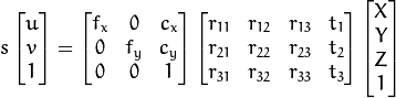 Variable Definitions:
 are the coordinates of a 3D point in the world coordinate space
 are the coordinates of the projection point in pixels
 is a camera matrix, or a matrix of intrinsic parameters
 is a principal point that is usually at the image center
 are the focal lengths expressed in pixel units.
![[R|t]](http://docs.opencv.org/2.4/_images/math/fad27ce6ccd005e429215a332c9d7a3a93c8246b.png) is the homogeneous transformation matrix derived from the homography matrix
is the homogeneous transformation matrix derived from the homography matrix
- OpenCV is used as the primary framework for this portion of the localization algorithm. Images are first converted from ROS sensor messages into OpenCV format images via the CVBridge ROS package. After converting the images, they are prepossessed using an intensity threshold value calibrated based on the exposure time of the camera. After the threshold is applied, a K-means algorithm is executed, identifying the centers each deck beacon. These centers are then paired with our “target image”, where the camera is orthogonal to the deck at some known distance. This allows for the computation of a homography matrix between our target image and our input image. This homography matrix can be combined with the matrix of camera parameters to solve the PnP problem and compute the 3D pose of the deck relative to the camera.
- The motion estimate for the rotorcraft.
- A Kalman filter is being utilized
- It combines information from the IMU, camera information, and the commands that are being sent to the rotorcraft to estimate the roll, pitch, yaw, and vertical velocity
- The motion estimate for the deck.
- This implementation is still in development
2. Trajectory Generation Algorithm
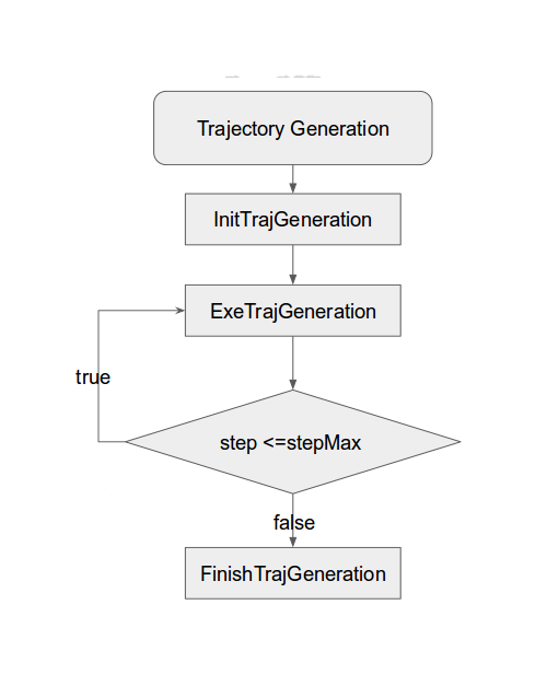
The trajectory generation algorithm for the quadrotor used the concept of the differential flatness and quintic polynomials to generate trajectories for x, y, z and yaw. The software flow is shown below.
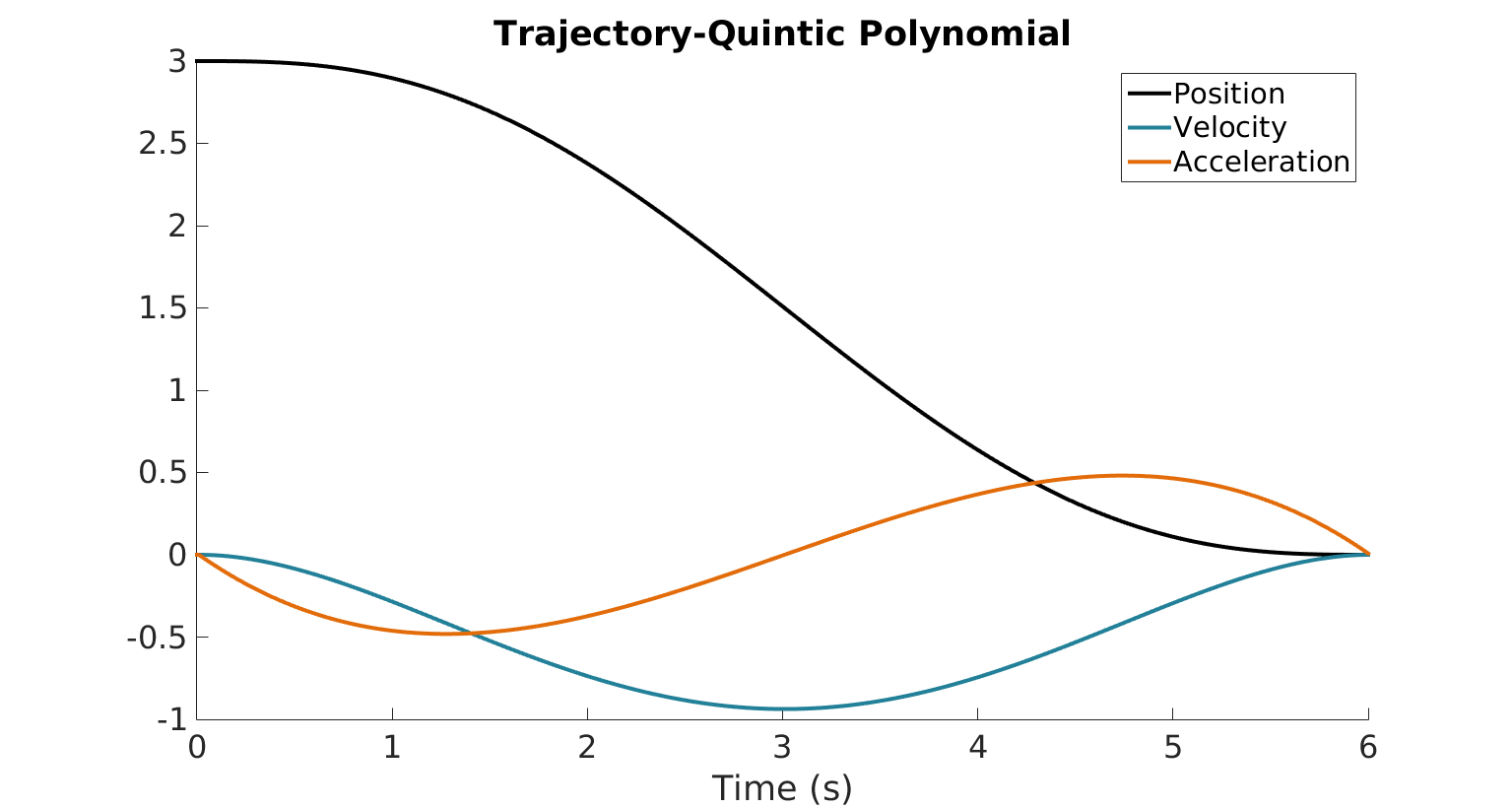
 And the trajectory command generated by the quintic polynomial is shown below:
3. Trajectory Follower subsystem
The trajectory follower subsystem is responsible for generating the flight commands to keep the quadrotor on its planned trajectory. This is achieved through the use of feedback from the state estimator.
4. Flight Control subsystem
The flight control subsystem is broken into two pieces:
- The flight control subsystem should subscribe to the commands from trajectory generation, trajectory follower, and landing algorithm subsystems. It will intake these commands and transform them into RC commands for the quadrotor.
- The signal distribution subsystem subscribes to the RC commands generated from the flight control subsystem. It decides which commands are sent to the flight controller of the quadrotor. In autopilot mode, this subsystem should send commands generated from the single board computer. In manual mode, it sends commands generated from the RC transmitter.
5. Prediction Algorithm
In this project, only the roll of the deck is predicted. All other motion of the deck is treated as noise and handled by the controller. The roll of the deck is observed and recorded. This information is analyzed in real time to determine when safe landing times are occurring. A safe landing time is defined such that the deck is flat compared to gravity. The time difference between safe landing times is calculated, and this time difference is filtered and propagated forward.
Several assumptions are made about the motion of the deck. The motion is assumed to be periodic. The period of motion has to be relatively constant on the time scale of about 4 cycles. The motion is also assumed to be symmetric. That is to say that the deck rolls just as far to the right as it rolls to the left, and spends the same amount of time on each side.