Final System:
12 February 2016
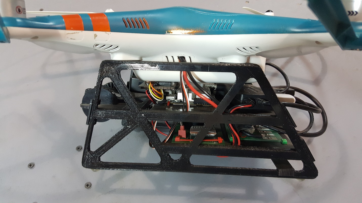
With the approval of the project sponsor and the course professor, the team has decided to re-scope the project to focus on the landing sequence during landing on a dynamically moving deck and remove the distance approach portion. This change allows for the simplification to one camera, which will be a fish-eye camera, in place of the short range camera and long range camera previously used. Additionally, using a fish-eye camera allows for fixed-mounting and the removal of the gimbal from the design. This frees up a good amount of space to mount additional sensors (height and optical flow) beneath the DJI.
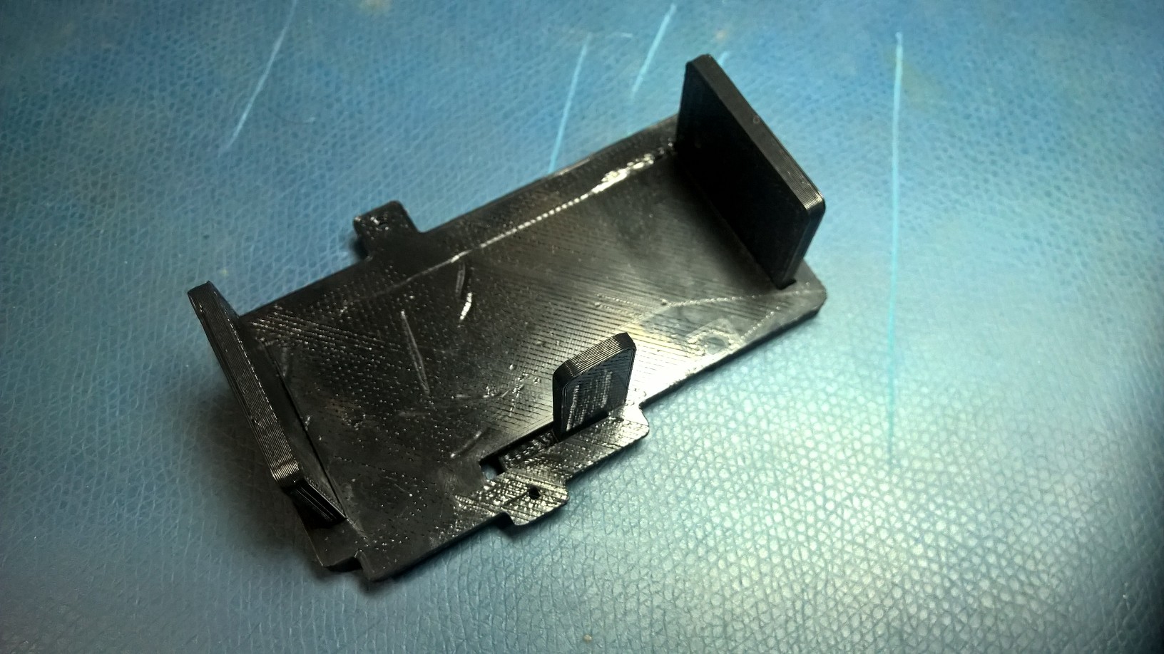
New legs have been designed in CAD and fabricated using the 3D printers. The legs have shelving slots for mounting hardware, which are much more stable than the previous hardware attachment method.
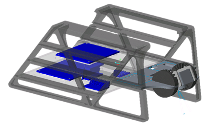
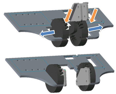
The front-most shelf of the legs has space dedicated to the height sensor, optical flow sensor, and the camera. The optical flow and height sensors are both downward facing with respect to the quad and the camera has several pitch settings. The ability to change the pitch of the camera will help with development, as the ideal angle for the fisheye camera has not yet been established. The pitch can be set from the camera facing directly forward to directly down, with 15degree intervals between each setting. It was designed for printing without support material on the 3D printer, as the use of support material can introduce significant errors in dimensions. The camera mount is printed in two pieces that assemble to the shelf using a press-fit. Side brackets are assembled to the camera, and the camera can be inserted into the desired angled slot using a press-fit. The small amount of compliance of the printed parts allows for snug fits and later changes to the pitch angle.
10 December 2015
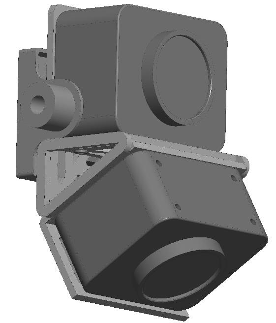
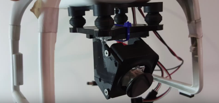
For the Fall Validation Experiment, the short range camera was fix-mounted to the rotorcraft at a 30-degree pitch angle from the forward facing direction. The gimbal is unusable due to the variable forces of the USB cables that attach to the cameras. Because flying is only required within short distances of the deck, only the short range camera was needed. The mount design for the camera is shown in the image below.
13 November 2015
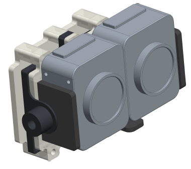
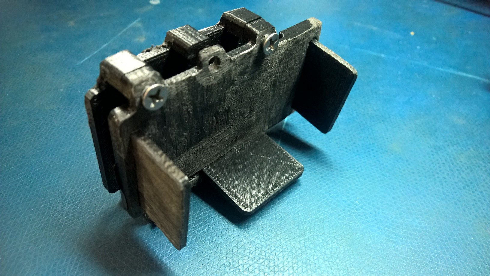
The previous design was found to be too bulky, therefore a similar design without the back panel was drafted, as shown in the picture below. The extra screw holes were removed, and the two remaining screw-holes will be enough to constrain the movement of the mount. The screw-hole locations and sizes were corrected to account for shrinking during cooling. The dimension between the camera side brackets was increased to account for cooling as well.
This model was 3D printed using the MakerBot, as shown below. This design allows both cameras to fit nicely between the brackets, and the screw holes are accurately placed.
6 November 2015
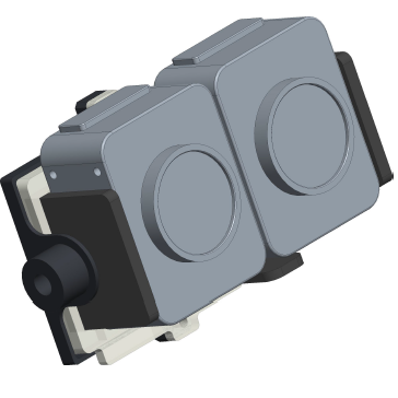
The design of the camera mount was changed to limit the height dimension. Since it is a gimbal attachment, it will be important for the size to be small enough to not contact the ground beneath the DJI when it is taking off and landing. Therefore, the leg length of the DJI constrains the size of the gimbal attachment. A sandwich style gimbal mount was drafted in CAD, as shown below. The cameras mount in a portrait view, which also allows the received image to capture a wider range in the vertical direction. This is preferred, as the yaw angle can be compensated for more easily than the pitch angle by the movement of the DJI. The directionality of the cameras is identical, which will allow for similar transformation computations for localization. The IMU was removed from the design, as it was determined that the IMU data should correspond to the movement of the DJI to provide control feedback for flight control.
The model was 3D printed using MakerBot, as shown in the picture below. The dimensions of the model shrunk slightly due to cooling after printing, so screw-hole placements and sizes were not adequate. Also, the dimension between the side bracket shrunk and is slightly too snug to fit both cameras. The portion of the mount behind the gimbal is too bulky to allow for free rotation of the gimbal on the quad.
28 October 2015
A CAD first draft of the camera mount was completed and is intended as an attachment for the gimbal of the DJI. The long range camera is oriented in the forward direction, with the short range camera angled 60 degrees down from horizontal. This design would allow both cameras to be mounted in a landscape orientation. The mount also includes space for the IMU.