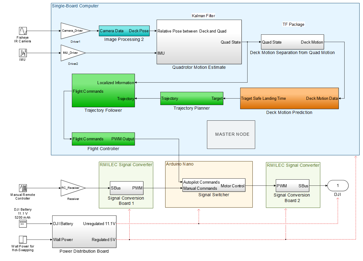
Figure: Software Architecture Block Diagram
Subsystem descriptions:
Vision Subsystem:
The vision subsystem is responsible for the detection of the ship deck and its relative pose. At long ranges, the position will be determined using the camera on the rotorcraft and the IR beacons on the corners of the deck. At medium range, all four of the IR beacons will be distinct enough for the camera to interpret individually. Finally, at close range, the known beacon pattern at the center of the deck will be sensed using the cameras. Alternatively, the vision subsystem could be replaced or augmented with radar and lidar components. However, the cost and complexity of these components is prohibitively expensive given their relatively minor benefits over the proposed subsystem.
Deck Marking Subsystem:
The deck marking subsystem is responsible for indicating several points of interest on the ship deck to the rotorcraft. The IR beacons on the corners of the deck provide an approximate location at long distance due to their greater than .5 mile visibility. Once the rotorcraft is close enough to distinguish between them, the center of the deck and the pose of the deck can be determined based on the prior knowledge of their configuration on the deck. Accounting for the optics of the camera’s lenses and their magnification, the scaled size and perspective warping of the beacons can also be used to calculate the distance to and relative position of the deck.
Localization Algorithm Subsystem:
The input to the localization algorithm will be the image from the short range landing camera, as well as the data from the rotorcraft IMU. Let long range be the range within which the deck beacons are within the field of view of the short range landing camera. Let prediction range be the range beyond landing range, but within long range, within which the system will attempt to perform prediction of the deck’s motion. Let landing range be the range where the deck is too close to localize effectively.
While at long range, the algorithm will identify the centroid of the four beacons and output the relative direction between the quadrotor and the centroid, using the known mounting configuration of the cameras to construct a heading for the quadrotor.
Once within prediction range, in addition to outputting the centroid location as above, the algorithm will also reconstruct the pose of the deck. To do this, the algorithm will identify the centroid of the beacons to determine the deck’s relative position as before. Then, relative pose will be determined by perspective transform of the known configuration of beacons on the deck. Finally, the “absolute” motion of the deck from one frame to the next will be determined by subtracting the quadrotor’s motion model data from the corresponding frames. This accounts for the motion of the quadrotor during the time between frames. This model is generated through a combination of the corresponding motion command from the path planner to the flight controller and the IMU data for the target time window. The prediction range algorithm will output both the absolute and relative pose of the deck.
Finally, within landing range, the algorithm will attempt to compute the relative and absolute poses as above, however, by this point we are likely incredibly close to the deck and need to be operating open-loop to land quickly.
Prediction Algorithm Subsystem:
The prediction algorithm will use the absolute pose of the deck over time to produce data of roll, pitch, and swell over time. This data will be in reference to an absolute world frame centered at the deck. The algorithm will then use a Kalman filter to predict the motion of the deck into the future. This will allow the rotorcraft to plan a trajectory such that it meets the deck at a relative high point and a relative flat point on the deck’s path. This is critical in order to perform a safe landing with minimal damage to the rotorcraft or the ship.
Trajectory Planning Subsystem:
The trajectory generation system is responsible for generating a trajectory from initial state to a target position. When the user triggers the autonomous landing system, the trajectory generation subsystem will receive current pose of the quadrotor from the localization subsystem and sets the pose as initial position. Then the trajectory generation subsystem will generate a trajectory based on a quintic polynomial from the initial position to the pre-defined goal position.
Trajectory Following Subsystem:
The trajectory following algorithm subsystem is responsible for detecting errors in our current flightpath and making the corresponding course corrections to put the rotorcraft back on the target trajectory generated by the trajectory generation algorithm.
The input command for the subsystem is the position trajectory generated by the trajectory generation algorithm, and the sensor feedback is the feedback data from state estimation algorithm. We use PD controller as feedback controller and use acceleration command generated by quintic polynomial as a feed-forward term. The advantage for using feedforward term is it can not only mitigate the following error but also decrease the amount of overshoot. Since there is an attitude controller controlled by DJI internally, we don’t need to add additional inner loop to control the attitude.
Rotorcraft subsystem:
The rotorcraft is responsible for executing the command sent from the single board computer such as flying, landing, and flight mode switching. The rotorcraft consists of flight avionics, actuators, radio transmitter and receiver, vehicle frames, and battery. Flight Avionics is the brain of the system; it consists of a processor, sensors, and input/output (I/O) pins. The basic sensor a rotorcraft requires is the gyroscopes, which provides the angular information of the rotorcraft.
However, without the accelerometer, the user needs to manually control the orientation of the rotorcraft. Typically, most flight controllers apply proportional-integral-derivative (PID) control for stabilization of the rotorcraft. The I/O pins are responsible for providing connections of actuators and command receiver to the processor. In this work, there are two inputs responsible for the dynamic movement of the rotorcraft. One is the trajectory command send by single board computer while the other one is from radio transmitter in case of emergency. For actuators, brushless dc motors are used; each of the motors is driven by electronic speed controller. The thrust of the vehicle is provided by attaching propellers on the motors. In the ideal situation, the rotorcraft should autonomously follow the exact planned trajectory under the influence of natural disturbance and in EMCON condition. Therefore, dynamic stability of the rotorcraft is the primary concern in this work since any disturbance to the rotorcraft could result in bias to the sensors. In the scope of rotorcraft platform trade study, the disturbances include wind, payload variation, and other factors. The rotorcraft should provide enough maneuverability and stability with the installation of single board computer, sensors and battery. Moreover, the landing gear should withstand multiple tests; so the cost can be minimized and the components can be protected. Finally, the application programming interface (API) and community support of the rotorcraft platform can be great sources to reduce development time.