fi
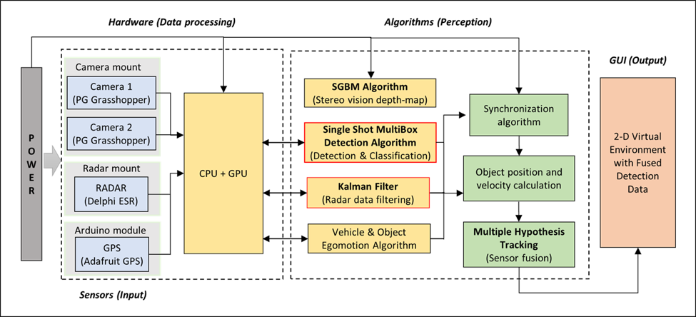
Figure 1. Cyber-physical Architecture of the system
- Hardware
The hardware section, represented on the left in Fig. 1, contains the power source, the sensors and the computer. The power source supplies DC power to the sensors and AC power to the computer (using a DC-AC power inverter). Different power sources were used during the course of the project. For indoor testing, we relied on a 30 V, 5 A DC power generator connected to the AC mains power supply. For testing the sensors on-board our car, we initially connected a small, 150-watt DC-AC inverter to a cigarette lighter socket of the car. Our power requirements grew when we decided to use a power computer for this project, and so the cigarette lighter socket was not a viable option (it could supply at most 120 W of power) later on in the project. We eventually decided to use a 1100 W DC-AC inverter connected to the car’s battery to power the computer. A 12 VDC voltage regulator and a 24 VDC step-up converter were also connected to the battery to power the cameras and the radar, respectively.
There are three sensor subsystems that make up our final system. We mounted a Delphi ESR 2.5 radar unit to the front of our car. We built a custom stereo vision subsystem composed of two identical cameras (PointGrey Grasshopper 3), which are mounted in the testing vehicle at a fixed baseline distance. Lastly, we use an Adafruit Ultimate GPS sensor connected to the computer via an Arduino Micro. In addition to providing our system with GPS data, the Arduino module also enables hardware triggering of the cameras via their GPIO pins. These three sensor subsystems together collect information about detected objects in the vehicle’s environment in real-time. All the raw data acquired is passed to the software perception module, where filtering, synchronization, and interpretation tasks take place. The processing unit essentially serves as the center of all communication for our standalone perception system.
- Software
The software section, represented on the right in Fig. 1, contains the algorithms and methods used to collect, store, and process the data flowing in and out of our system. The CPU of our computer is programmed to run all our calculations except for the stereo-vision object detection and classification. The SGBM algorithm runs on the CPU and is used to calculate the stereo-vision depth-map. Stereo-vision-based object detection and classification is done by running the SSD algorithm (Single Shot MultiBox Detector) on our Titan X GPU using CUDA. Our various algorithms yield processed data that together contain all the information needed to create the virtual environment. Object positions and velocities are computed independently by the vision subsystem and the radar subsystem. These values are correlated between subsystems (and sensor fusion is thus achieved) by using Multiple Hypothesis Tracking (MHT) on the detected points, based on position.
For object detection and classification, we use the state-of-the-art Single Shot MultiBox Detector (SSD) algorithm on the left camera image. The SSD algorithm involves the use of a deep neural network, which is why it achieves both object detection as well as object classification at high speeds with high accuracy. Based on experimentation, we found this algorithm to have a relatively good balance between performance (detection rate and accuracy) and speed (number of frames processed per second).
Aspects of the cyber-physical architecture have been updated many times since the start of the project to reflect new system developments and key decisions. For example, we decided to use a GPS sensor unit for our position and velocity ground truth. Initially we had considered reading that data from the car’s OBD port or from an IMU sensor instead. As mentioned earlier, we found that the pre-clustered targeting data that obtained from the radar directly was too noisy to be useable. Instead, we chose to use our own Kalman-based filter on the detection-level object positions obtained from the radar, because we found that this was a much more reliable method for detecting and tracking objects using the radar. Lastly, we found that although our stereo-vision subsystem could reliably identify objects within ~30 meters, it could not accurately determine their positions or their velocities. We thus included a position-based Multiple Hypothesis Tracking (MHT) algorithm for sensor fusion. This algorithm uses the filtered radar data to improve overall object detection accuracy by over 10% (compared to solely vision-based object detection).