The team has successfully fabricated a printed circuit board (PCB) for distributing power to the sensors on the testing vehicle, as shown in the picture below. Its functionality has also been tested in the lab.
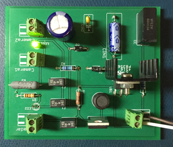
Figure 1. Power distribution PCB
The vehicle’s battery supplies the power input to the PCB through the cigarette lighter socket, which can provide a DC voltage at 12 volts. The PCB can distribute the power to the two cameras at the same voltage. It also contains the power boosting feature, which converts the voltage from 12V DC to 24V DC to power the radar. To protect the sensors from unnecessary damage, fuses and diodes with appropriate values are applied at each output port to prevent overpowering the sensors beyond their limits. Specifically, a fuse with a rated current of 2A and a fuse with a rated current of 500mA are used for the cameras (with the operational current around 1.5A) and the radar (with the operational current around 350mA), respectively.
Note that the design of this PCB does not take the power consumption of any additional device to the current system into consideration, for example, a computer with heavy-duty processing units (CPU and GPU) that might need to be equipped on the testing vehicle for more advanced perception tasks in the future.