The drive system consists of the drivetrain, Electronic Speed Controller, steering servo, and Teensy. This subsystem provides the actuation for our robot. Our final implementation allows us to control throttle(wheel speed) and steering angle through ROS geometry_msgs::Twist messages.
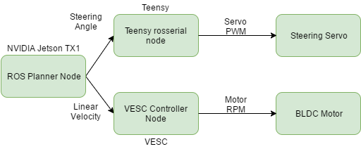
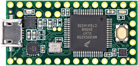
The navigation stack generates and sends a velocity and steering angle command via the ROS framework to the rosserial node, which then sends the command to the Teensy microcontroller. The Teensy maps the received commands to a PWM command through an empirically determined transfer function, and sends the corresponding signals to the robot’s Electronic Speed Controller and steering servo, allowing the robot to drive and steer itself.
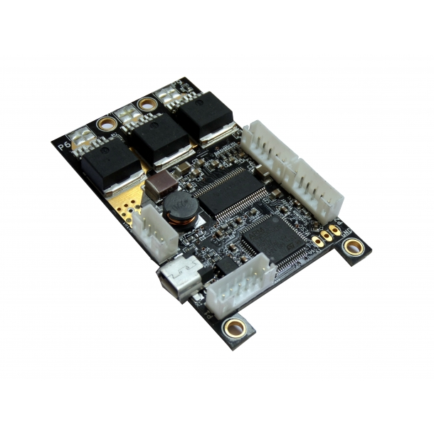
For the spring semester, we switched to a new RC car platform that uses a sensored brushless DC motor instead of a brushed DC motor. This promised greater control over the motor speed, and we exploited this advantage by also switching out the stock ESC for a custom one, the VESC. With this setup, we were able to perform PID wheel speed control using the hall sensors in the motor, and the processing and modulation was done by the on-board processor of the VESC.
Another step-up was that we can now use serial commands over UART to communicate with the VESC, directly issuing a desired ERPM (electronic revolutions per minute), and the VESC will handle the rest of the computation. This provides better precision and reliability over our previous control method, which relied on noisier PPM signals generated from the Teensy.
The VESC’s firmware tool allowed us to tune the PID gains via a GUI. In order to control the RC car at desired linear speeds, we had to empirically determine the wheel speed to ERPM gain using a laser tachometer. Another consideration while tuning the PID controller was the acceleration profile of the motor. We had initially started with a tuning that provided a smooth acceleration profile, as it felt the most natural for teleoperation. However, we had to re-tune the gains to maximize the instantaneous acceleration, as our dynamic simulation model made an assumption that the desired wheel velocities can be instantaneously achieved. In addition, the cost function of our planner was also constructed such that the control sequence generated is optimized for a smooth acceleration.
We also have teleoperation set-up with a Logitech joystick controller, which can override commands issued by the navigation stack. This is used for testing and emergency situations.
Given that our system has multiple command inputs from teleoperation, the ROS navigation stack planner, and our own iLQR planner, we needed a multiplexer to assign priorities to each of these incoming commands to avoid any conflict. For this functionality, we added the twist_mux ROS package to our launch stack, assigning the highest priority to the joystick commands to provide an option for manual override as a safety feature. We also monitored the timestamps of the messages to verify that this additional multiplexing operation did not result in any significant delay in the execution of the commands.