We have broken down our system tests into Fall and Spring Validation Experiments. They are outlined in detail below, as well as in these documents: FVE, SVE.
In addition, we have made a complete test plan for the Spring Semester with intermediate goals and verification. The document can be seen here.
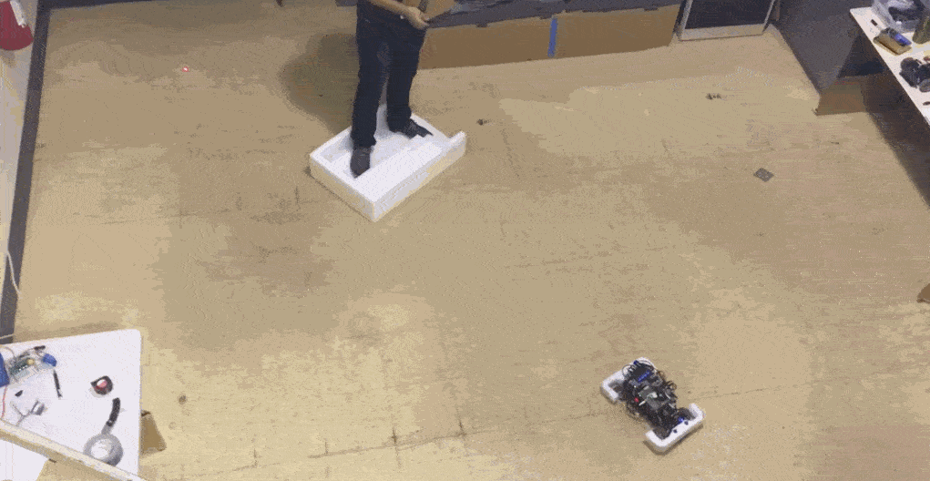
[Completed] Spring Validation Experiment – Apr 26/ May 3

Location: Newell-Simon Hall, B floor
Test setup
- Size: minimum 6m x 3m space
- Floor surface: Smooth tiling
- Static obstacle: 0.15m x 0.15m x 0.2m or larger
- Road: 2 lanes
- Lane width: 0.60m*
Initial procedure for all tests
- Initialize robot in known environment, on the right lane of the two-lane road.
- Send command velocity : straight forward with constant velocity of 3 m/s** while staying in the lane.
- When front of robot is ~1.5 m away from predetermined obstacle position, the obstacle will be introduced.
Demonstration procedure 1
- Initial procedure (see above)
- The robot will see the obstacle and execute an emergency brake.
- Observe the resulting trajectory of the robot.
- Robot will crash into obstacle in its attempt to come to a stop.
Demonstration procedure 2
- Initial procedure (see above).
- When the obstacle is introduced, the human operator will be given manual control of the vehicle via a joystick. The operator will attempt to avoid the obstacle.
- Observe the resulting trajectory of the robot.
- Repeat steps 1-3 three times.
Test procedure
- Initial procedure (see above).
- The robot will see the obstacle and execute a maneuver around it, while staying within the limits of the adjacent lane.
- Observe the resulting trajectory of the robot.
Success criteria
- Robot detects obstacle on current path (show on laptop).
- Robot avoids contact with obstacle
- Robot resumes its original trajectory (straight forward) along the lane.
- Robot stays within road markings throughout the test.
* US Highway typical lane width: 12 feet (3.7m); at 1/10 scale, lane widths will be about 0.37m. However with our crash bumper, the footprint of the robot is enlarged by 1.5 times, requiring a lane width of >0.55m
** Freeway speeds are usually > 60mph ~= 2.7 m/s at 1/10 scale. Moose tests are typically conducted around 40mph ~= 1.8m/s
[Completed] Fall Validation Experiments – December 1st/8th
Location: Newell-Simon Hall, B floor
Test setup
- Size: minimum 6m x 4m space
- Floor surface: smooth tiles or concrete
- Static obstacles: 0.15m x 0.15m x 0.2m or larger
Test procedure
Test 1: Localization Accuracy Test
- Mark 3 points in test environment with tape
- Initialize the robot at any one of the points
- Tele-operate the robot to any one of the other marked points
- Obtain the position estimate of the robot
- Compare the position estimate with the true coordinates of the marked point
Test 2: Navigation and Obstacle Avoidance Test
- Place one or more obstacles in the environment, which are not part of the known map
- Initialize robot with known map
- Send goal point via GUI
- Robot will travel from start point to goal point at a commanded velocity of 1 m/s
- Measure the distance of the robot from the goal point
- Repeat steps 1~4, two more times
Test 3: Simulation model for drifting
- Input commands and initial conditions to Simulink model
- Observe animation of the simulated motion of the robot
- Input an equivalent set of commands (steering angle, throttle) to robot
- Observe motion of robot in real world
Success criteria
Test 1: Localization Accuracy Test
- Robot outputs an estimate of its position, relative to the map
- Position: Robot localizes itself within 0.15m of each marked point
Test 2: Navigation and Obstacle Avoidance Test
- Robot plans an initial trajectory to its destination
- Robot sends updates of its planned trajectory and map to GUI
- Robot avoids known and unknown static obstacles
- Robot reaches planned destination coordinates within 0.15m
Test 3: Simulation model for drifting
- Model is able to drift in a predictable fashion in the simulation
- Robot is able to achieve drifting behaviour in real world test