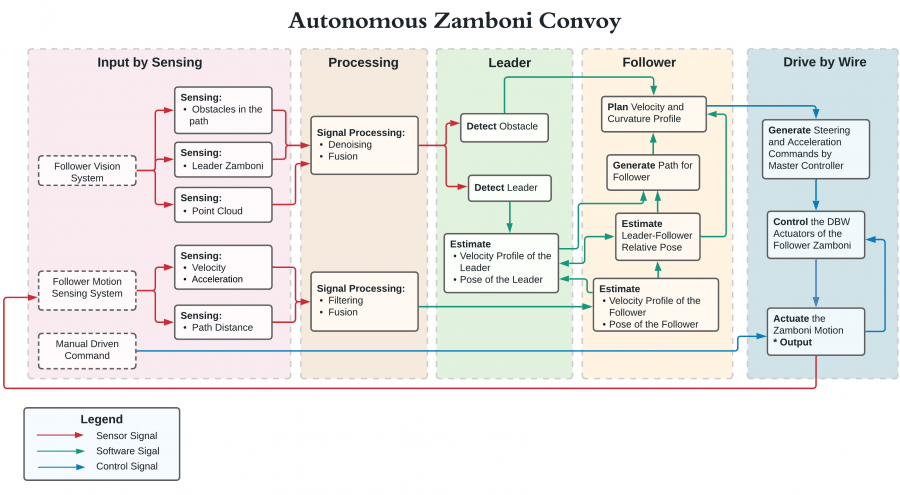
The functional architecture in Figure 1 shows the subsystem functions and the flow of sensor, software and control for autonomous Zamboni convoy. The functional architecture is broken up into five modules: input by sensing, processing, follower, drive-by-wire which contain different sub-systems described by functional requirements.
Input by sensing:
The inputs to autonomous Zamboni system are sensor signals captured by Follower Vision System and Follower Motion Sensing System, and the Manual Driven Command come from human driver. Vision system shall sensing the obstacle, leader Zamboni and the environment which will be used as input for perception in software. Motion sensing system shall capture the follower vehicle’s motion state and then enable the driving behavior control in autonomy.
Processing:
The processing functional module involves functions of denoising, fusion, and filtering of all the raw data. The signal processing process shall go on in real-time in actual function scenario.
Leader:
The leader module describes the function requirements that involves the leader Zamboni vehicle. Obstacle is also included in this module as another detection object in front of the follower vehicle. Based on the leader detection, the system shall be able to estimate the velocity profile and pose of the follower, which serves as an input for follower’s autonomy system.
Follower:
The follower module encapsulates the required software-level functions for the follower vehicle. The motion information captured by sensing system goes directly to the follower modular to estimate the velocity profile and pose of the follower. Meanwhile, the leader’s motion profile shall be updated in succession using the estimation of the follower thus there is a two-way software signal exchange connecting both leader and follower module. Then combining both leader and follower’s information, the system shall estimate their relative pose, which is used for path generation. The motion planning block shall then get input from obstacles, path points and relative pose to provide desired velocity and curvature profile.
Drive-by-wire:
The drive-by-wire module corresponds to the requirements of converting current Zamboni vehicle to a drive-by-wire platform. After motion planning the control signal is transmitted to the drive-by-wire modular to generate the steering and acceleration commands by master controller first. The motion controller block will take the command before sending actuation signal and simultaneously receive the feedback from the actuation block. The actuation and motion block is the final output of the entire system, it receives signal from controller or directly from manual commands. In addition, the actuation and motion information will also be captured by the sensing which forms another close loop.