The cyberphysical architecture in Figure 1 illustrates in detail the subsystem components that correspond to the functional modules in Functional Architecture and incorporates design decisions based on the trade studies. The cyberphysical architecture is broken down into six major modules – Zamboni Vehicle Structure, Sensing, Signal Processing, Follower Autonomy, Drive by Wire Controller and Manual Switch. These modules deals with five different kinds of of signals, as our signal flow it includes sensing, algorithm, can bus, electrical and mechanical signals. The following section explains in detail how individual systems function and interact with each other.
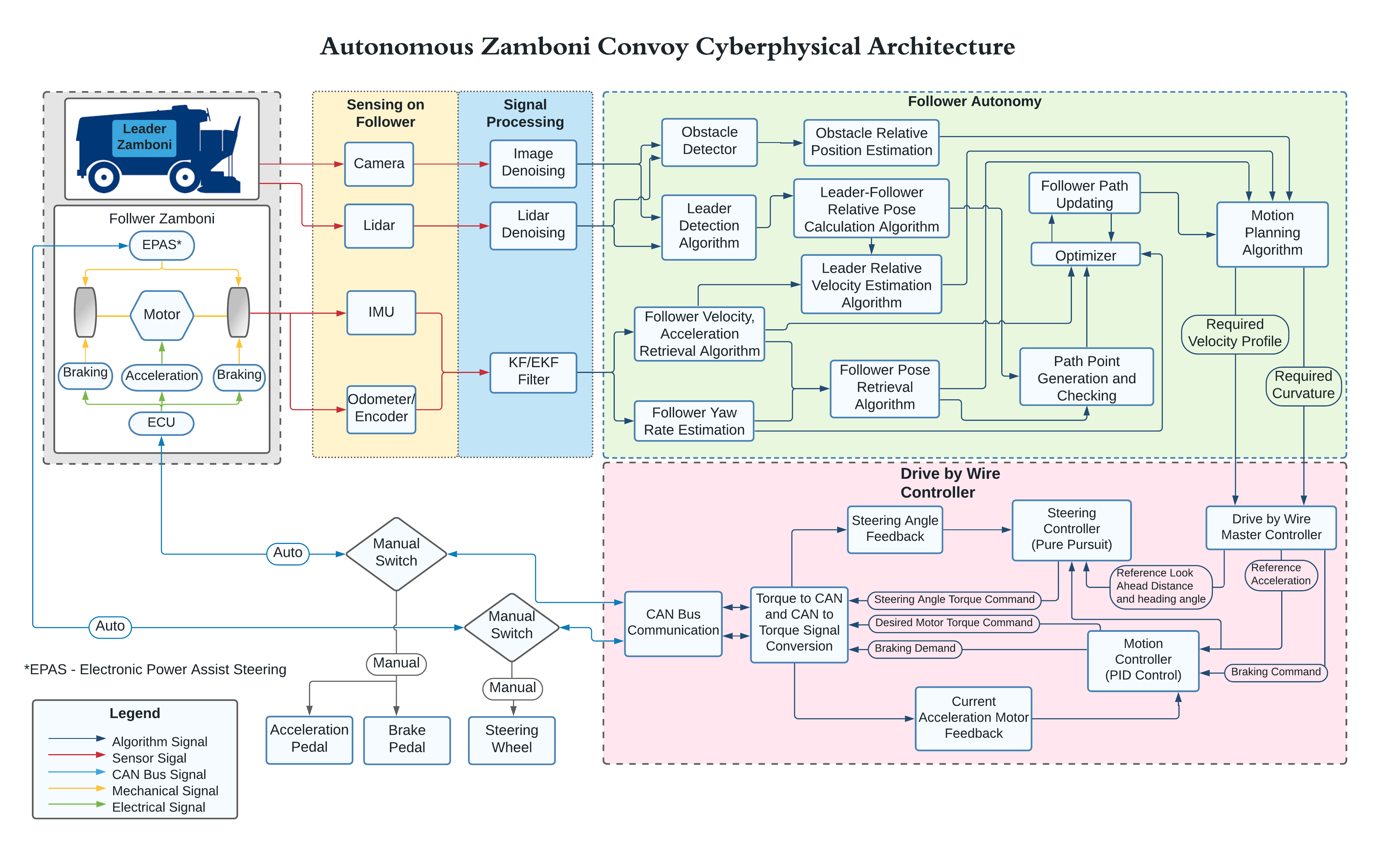
Zamboni Vehicle Structure:
Based on Zamboni platform trade study, the electric Zamboni platform is chosen as our follower system. The whole vehicle structure includes the ECU hand- ing electrical signal and motor and electronic power assist steering (EPAS) handing the mechanical signal.
Sensing and Signal Processing:
According to the vision subsystem trade study, we deter- mined that follower’s vision system is composed of stereo cameras and a Lidar, used for detect- ing and estimation of the leader or obstacle in front of the follower. The vision signal requires denoising process before go to the autonomy software modular. As for the follower’s motion sensing system, we use IMU and Odometer (encoders) to sense the motion signal of the vehicle. These motion signals then go to a filter (e.g. Kalman or Extended Kalman Filter) to get fused and will be used for estimation in the autonomy modular.
Leader-Follower Autonomy:
The main function of this module is to deal with the autonomy software part and finally generate the required path and required velocity of the follower. This information is then used by the drive by wire controller subsystem to send appropriate commands to the respective actuators to actuate the Zamboni movement. This part of can be further divided into following major sections:
- Leader Information Extraction. The information coming from the vision subsystem is used here. The main task of this subsystem is to detect the leader in the environment and incorporate the motion information into the frame of reference of the follower.
- Follower Information Extraction. The fused sensor data of odometer and encoder is used here to estimate the current pose and the current yaw rate of the follower. This data is then used to generate the waypoints/paths and plan the motion for the vehicle.
- Leader-Follower relative pose estimation. This block estimates the relative pose of the leader with respect to the followers pose and yaw rate, using the detection of the leader.
- Follower path generation. The main task of this block is to generate waypoints for the follower based on its current pose and generated waypoints. These waypoints generated are optimized by the optimizer block based on the physical and system constraints of the Zamboni.
- Follower Velocity profile generation Follower velocity profile generation block estimates the velocity profile the follower has to have based on its current velocity and the estimated velocity of the leader.
- Motion Planning. The motion Planning block makes sure that the follower follows the path generated by calculating the heading rate required and the required velocity profile it will have based on the environment (if obstacles detected).
Drive by Wire System:
Drive by Wire system is another main section of the system which requires converting of current vehicle platform. Its main objective to control the motion of the Zamboni so that it follows the path generated and maintains the required velocity profile. This subsystem consists of the master controller which sends appropriate commands to the steering controller and the motion/velocity controller. The master controller sends the required heading angle and lookahead distance of the waypoint, based on which the pure pursuit steering con- troller generated the necessary steering commands to steer the Zamboni as per the requirement. Another important function is to send the appropriate acceleration and braking commands to the Zamboni so that it follows the required velocity profile. This subsystem makes sure that the generated actuation commands are compatible with the Zamboni’s communication channel so a can bus communication module is included. The system also has a feedback from Zamboni’s inbuilt hardware.
Manual Switch:
This module makes sure that there is an interface where the user can switch between autonomous and manual mode of driving of the Zamboni as per requirement. This module human can take over the controller outside the ice rink or in emergent case.