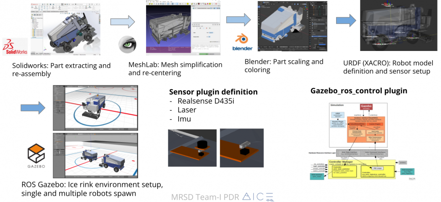
The URDF file for the Zamboni vehicle was developed first, which had an Ackermann steering mechanism. To better organize the model description, XACRO was used to build the vehicle model. For better visualization, a detailed mesh file for the Zamboni was developed, which was exported from the Solidworks CAD model provided by the sponsor. However, the CAD model has over 1,000 parts describing all the details of a car. We combined all the parts into only five: the four wheels and a car body and exported them as mesh files. Due to the complexity of the original mesh file, gazebo will get stuck when loading the vehicle. Thus, we used MeshLab to simplify the faces and vectors on of the mesh file, deleting unnecessary detail while keeping the major outer appearance. Finally, Blender was to change the scale, center position, and more importantly, the color of each face.
Since we will command the motion of the vehicle by sending steering and velocity command to gazebo, we used gazebo_ros_control Gazebo plugin. It provides a pluginlib-based interface to implement custom interfaces between Gazebo and ros_control for simulating more complex mechanisms. The ros_control packages take as input the joint state data from your robot’s actuator’s encoders and an input set point. It uses a generic control loop feedback mechanism, typically a PID controller, to control the output, typically effort, sent to your actuators. ros_control gets more complicated for physical mechanisms that do not have one-to-one mappings of joint positions, efforts, etc but these scenarios are accounted for using transmissions. By tuning the PID, the Zamboni vehicle finally react very fast after sending the command.