Full System
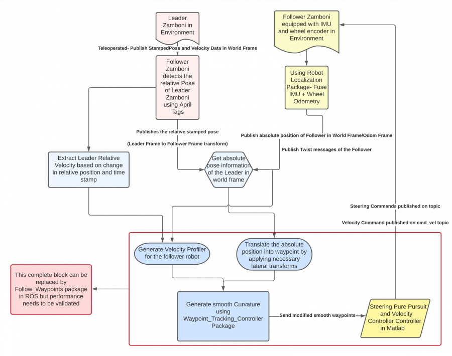
Figure 1 showcases the entire algorithm design of our system given a drive-by-wire Zamboni. More detailed descriptions and explanations of our full system design can be found here.
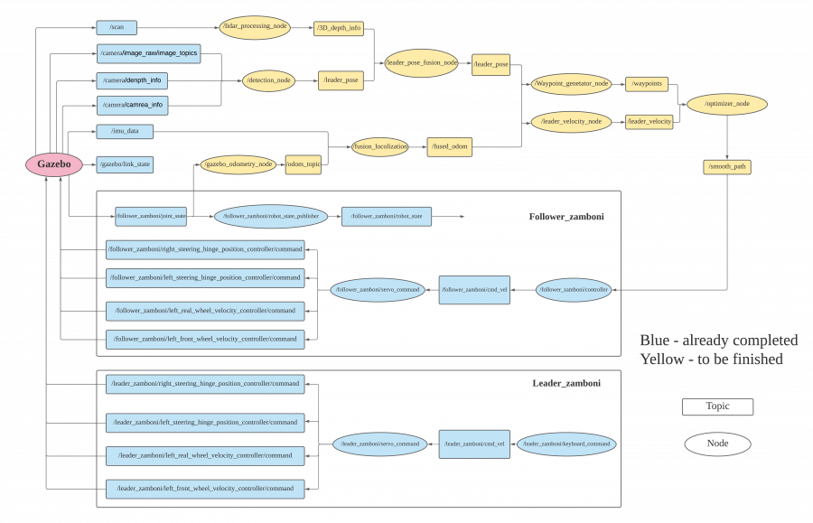
Figure 2 below shows our most recent design of the entire system in simulation, represented by the ROS Node Map.
Subsystems
Zamboni Platform
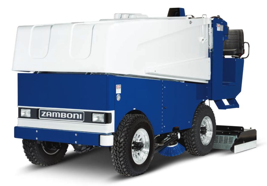
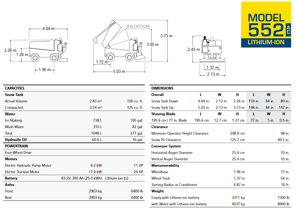
As of the writing of this report, the team has been promised a Model 552AC Lithium-Ion Zamboni to be used as a platform for retrofitting the drive-by-wire system and the autonomy software. Since the motivation behind this project was to autonomize an ice-resurfacer, specifically for Zamboni, not much choice was afforded in selecting a platform. The team requested one of their electric models, such as the Model 552AC that will be received, so that less work would have to be done when designing and implementing the drive-by-wire system than if an internal combustion model was provided as a platform. A picture of the Model 552AC Zamboni and some of its specifications are shown in Figures 3 and 4.
Sensing and Processing
The sensing subsystem is composed of two major modules: Follower Vision System and Follower Motion Sensing System. As the subsystem trade study, we will use a stereo camera and a LiDAR.
We choose Intel RealSense D435i as our stereo camera solution attribute to its small size, ease of use, and 10-meter maximum depth detection range. It has a wide field of view and global shutter combination that offers accurate depth perception when an object is moving or a device is in motion, and it covers more area, minimizing blind spots. Moreover, this camera will additionally provide the RGB visual data for object detection and depth image to localize the object. As for LiDAR sensor, we choose the Velodyne VLP-16 Puck LiDAR sensor which is available for loan from the MRSD inventory without cost. The VLP-16 has a range of 100m, and the sensor’s low power consumption, light weight, compact footprint, and dual return capability make it ideal for our system according to the system-level requirements.
The motion sensing system contains Inertial Measurement Unit (IMU) and Odometer. The chosen Intel RealSense D435i has an internal IMU with 6 degrees of freedom so it removes the need to mount an external IMU, reducing cost and complexity. However, the mounting position of the sensor require further design to make sure we get accountable reading data. The odometer will rely on the inbuilt encoders of the Zamboni vehicle.
Necessary denoising algorithm is required on the RGB visual data before being used for depth calculation and object detection. Data fusion is designed especially for depth recovering, which will influence the accuracy of leader’s relative pose estimation. Depth and leader position information can be derived either camera or LiDAR only, however, a fusion will help ensure the accuracy as stated by R.P.03 and R.P.12. The IMU and odometer data will be used for vehicle pose estimation. A Kalman or Extended Kalman Filter will be used for follower’s state estimation.
Alternatives: An alternative stereo camera could be Stereolabs ZED. And Intel RealSense LiDAR Camera L515 could also be an alternative which has an RGB camera, gyroscope, and accelerometer to round out the capabilities for high-quality performance and use case flexibility. Another option is to use monocular camera to do detection and the depth data will rely on LiDAR only.
Obstacle Detection
The obstacle detection subsystem aims to detect objects on the desired trajectory of the follower, such as humans and goals. The depth information obtained from the point cloud after sensor fusion as well as the RGB image from the camera are taken as inputs for the YOLO ob- stacle detection algorithm. A pre-trained model, such as the one trained on COCO dataset, will be used to detect obstacles on a hockey rink, such as humans, goals, or the mascot.
The input images from stereo camera will be split into grids, and then each cell is responsible for detecting those target whose centroids fall within that grid. Each cell will predict a bounding box and the confidence score of the bounding box. Each grid cell also predicts conditional class probabilities, which are conditioned on the grid cell containing an object. The final detection box can be obtained by multiply the conditional class probabilities and the individual box confidence scores to generate a class probability map.
Finally, a decision-level fusion based on weighted-mean method can be applied to the detection outputs of depth image and RGB image to generate the final obstacle detection result.
Alternatives: If the YOLO doesn’t work well due to it sacrificing accuracy for detection speed, we will try other variants of YOLO, e.g. PP-YOLO, or switch to Single Shot Detector (SSD), which achieves a good balance between accuracy and speed.
Leader Detection
This subsystem serves to extract information about the leader Zamboni that can be used together with the follower’s information to generate a trajectory. In terms of the detection of the leader Zamboni, this subsystem will be similar to the previous one for obstacle detection, i.e. utilizing YOLO to detect and locate the leader. Differently, we will not train a model on a dataset of Zamboni images; instead, we will stick a large QR code on the back of leader Zamboni and train the YOLO to detect only the QR code. Along with the sensor data, we will be able to determine the position of the leader. Based on leader’s positions in previous timestamps, the subsystem calculates the relative pose of the leader. Moreover, after calculating the follower’s velocity, obtained from the subsystem that is introduced in next subsection, the relative velocity of the leader is retrieved. Altogether this subsystem computes the leader’s pose and velocity relative to the follower so that the trajectory can be generated accordingly.
Alternatives: Similar to the Object Detection Subsystem, if YOLO fails, we will switch to other variants of YOLO or SSD. If the leader information couldn’t be extracted correctly, other methods of obtaining the leader pose and velocity will be investigated, such as wirelessly communicating the information between the leader and follower.
Motion Planning
This subsystem serves to extract information about the follower Zamboni and to generate as well as optimize the trajectory to follow, based on the information obtained from the previous two subsystems. First off, the follower Zamboni’s velocity, acceleration, and the yaw rate will be retrieved or estimated based on the fused readings from IMU and the odometer, which will then be utilized to retrieve the pose. Together with the relative pose of the leader as estimated in the previous subsystem, a preliminary set of waypoints is generated. Then the waypoints are optimized and updated so that it’s not against any constraint of the Zamboni dynamics, e.g. an unrealistic turning radius. Lastly, based on the obstacle detection results, a motion planner will decide either to stop the follower if any obstacle appears on the trajectory, or to continue to follow the leader with the same velocity as the leader’s which is obtained previously. Altogether, the motion planning subsystem will output the desired velocity profile and curvature required by the drive-by-wire controller.
Alternatives: Should the motion planner not output desired velocity profile and steering profile due to incorrect follower’s extraction, a relative localization approach would be used. For example, the subsystem will utilize detections of some landmarks in the ice rink to localize the follower, and hence retrieve the position, velocity, and pose.
Drive-by-Wire
The drive by wire subsystem is one of the major subsystems of the autonomous Zamboni convoy system. The main function of this system is to equip the Zamboni with essential sensors and actuators to control its motion electronically. The system is divided into: Steering Controller, Motion/Velocity Controller, CAN Bus communication.
The steering controller system consists of the master controller which sends appropriate commands to the steering controller and the motion/velocity controller. The master controller sends the required heading angle and look-ahead distance of the waypoint, based on which the pure pursuit steering controller generated the necessary steering commands to steer the Zamboni as per the requirement.
The velocity controller will send the appropriate acceleration and braking commands to the Zamboni so that it follows the required velocity profile. All the actuators of the Zamboni are controlled via CAN Bus so the drive by wire subsystem also converts all the actuation commands into appropriate CAN Bus signals.
Alternatives: Should the team be unable to convert the Zamboni to drive-by-wire, some or all of this subsystem will be offloaded to the sponsor, Locomation, and/or Zamboni; the team would then focus on the sensing and autonomy portions of the project.