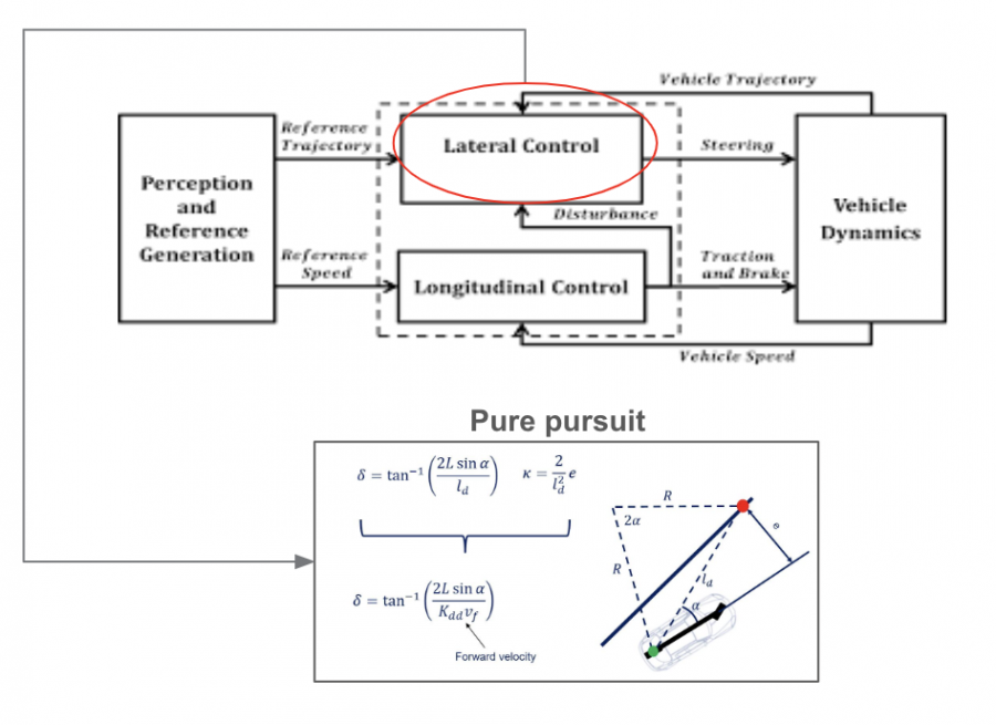
The main function of the control subsystem is to generate the low-level control commands that will be sent to the drive by wire actuators to control the motion of the follower. To make the control task easier, we have divided the subsystem into 2 main controller subsystems:
a. Pure Pursuit Lateral Controller
Pure pursuit is a path tracking algorithm. It computes the heading angle which is used to compute the steering angle command that moves the vehicle from its current position to reach some look-ahead point in front of the robot. The linear velocity is assumed constant, hence you can change the linear velocity of the robot at any point. The algorithm then moves the look-ahead point on the path based on the current position of the robot until the last point of the path. You can think of this as the robot constantly chasing a point in front of it. The property LookAheadDistance decides how far the look-ahead point is placed.
The inputs of the lateral control subsystem are the follower local path from the Planning Subsystem and the follower current pose from the Localization Subsystem. The output is steering commands. The subsystem is shown in Figure 1.
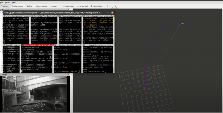
Test 1. Waypoint Following on ATV
We tested the waypoints following on ATV to test the lateral controller as shown below. The follower was able to follow a prerecorded path.
Test 2. Leader Following on ATV
Instead of following a prerecorded path, we tested the lateral controller by combining perception subsystem. The follower was able to follow the leader’s path with pure pursuit controller.
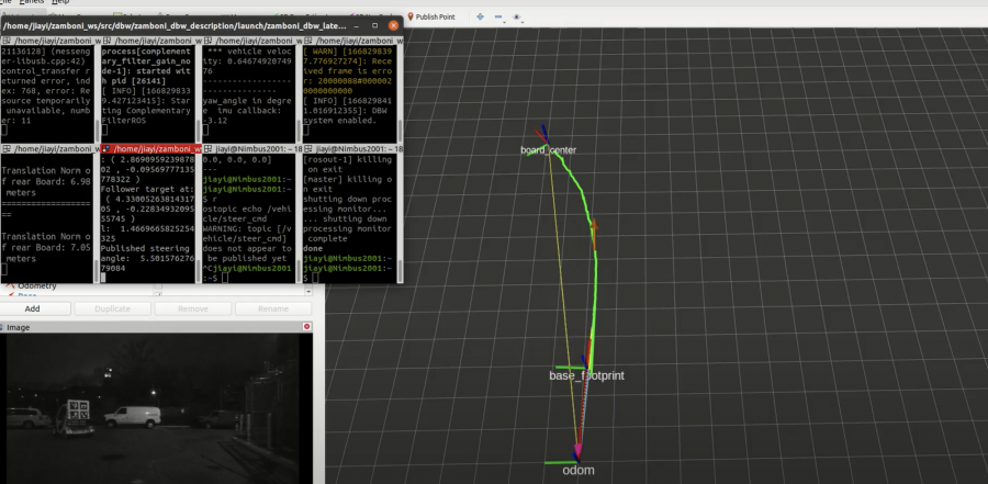
Test 3. Waypoints Following on Zamboni Ice Resurfacer
We tested the waypoints following to test lateral controller as shown below. The follower wad able to follow a prerecorded path.
Test 4. Leader Following on Zamboni Ice Resurfacer
We tested the lateral controller by combining perception subsystem. The follower was able to follow the leader’s path with pure pursuit controller.
b. PID Longitudinal Controller
A PID longitudinal controller is used to get the target velocity of the vehicle, so that the follower is able to follow the leader with a constant longitudinal distance. The inputs of longitudinal control subsystem are the follower target pose from the Planning Subsystem and the ollower current pose from the Localization Subsystem.
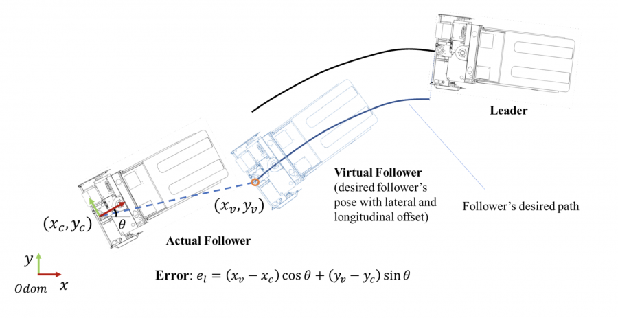
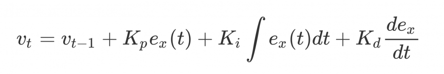
From Figure 4, the longitudinal error ex between the target position and the current position of the follower can be calculated. The target velocity of the follower is assumed to be an equation as:
For DBW Zamboni vehicle platform, the velocity is controlled by the position of the throttle pedal. Therefore, the velocity in the equation is actually the percentage of throttle value.
Test 1. Longitudinal Control Testing on ATV
We tested the longitudinal controller on ATV by following the leader in a straight path as shown below.
Test 2. Longitudinal Control Testing on Zamboni Ice Resurfacer
We tested the longitudinal controller on Zamboni ice resurfacer as shown below. The vehicle was able to slow down and stop when the distance to the leader was less than the threshold.