Back-up Platform
A few weeks into the spring semester, we received news that the delivery of the Zamboni would be delayed until March or April. Since this would leave too little time for us to become familiar with the Zamboni, integrate our sensors and software onto it, and do the necessary testing before the Spring Validation Demonstration, we decided to use an RC car as a back-up platform. Doing so would allow us to do physical testing of our sensors autonomy stack during the spring semester before scaling up to the actual Zamboni in the fall.
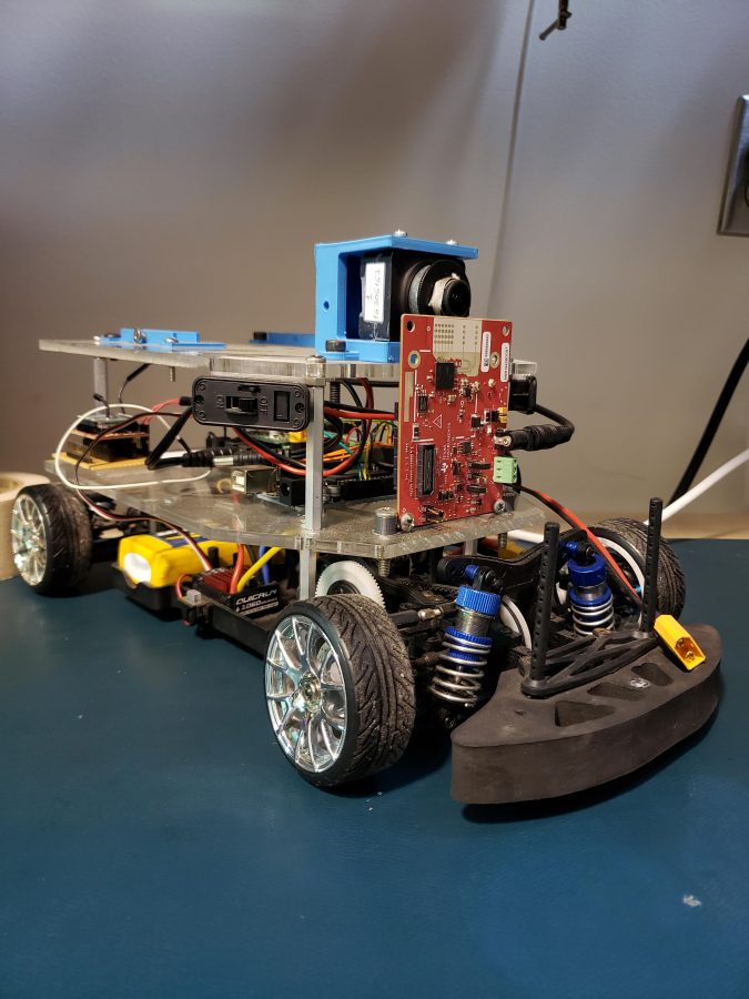
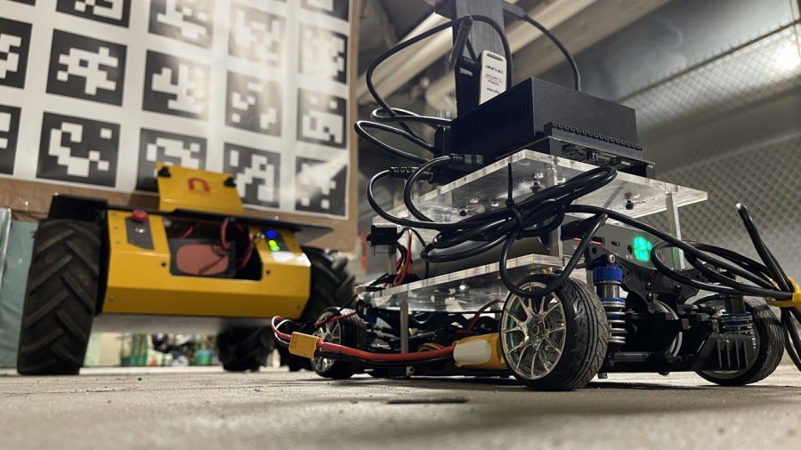
We decided to use an RC car previously used by 2 other MRSD teams since it was readily available, would be compatible with ROS, had pre-existing sensor mounts, and appeared to have an Ackermann steering geometry similar to that of the Zamboni. The RC car as we received it mid-February is shown below.
Once we obtained the RC car, we began to strip it of all of the external sensors and hardware that the previous team had added until we were left with the base driving and steering systems. The steering system consists of a single servo motor that actuates a linkage between the two front wheels. By measuring the maximum wheel angles that could be achieved, we developed a simple linear mapping between the servo angle and the angle of the front right wheel. The speed of the RC car is controlled using an ESC connected to a brushed DC motor. After some experimentation and research online, we were able to figure out how to send commands to the ESC to achieve a desired speed given an assumed linear mapping.
Once we got the RC car’s basic functionalities (i.e., steering and accelerating) up and running, we did some basic straight line testing to check their performance. During these tests, we noticed a problem with the steering mechanism of the RC car: the wheels were not aligned properly. This would cause the car to drift significantly when it was supposed to be driving straight. Looking through some of the past teams’ documentation revealed that there had been a crash, and that afterwards a slight offset to the steering angle was required. After testing various offsets, we found the one that resulted in the straightest path possible.
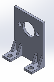
With the RC car now able to follow speed and steering commands, we began adding the sensors we would need onto the car. The first of these was the RealSense D435i camera. The mount for the camera is shown below.
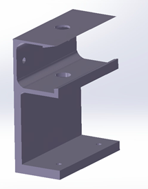
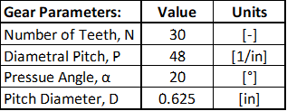
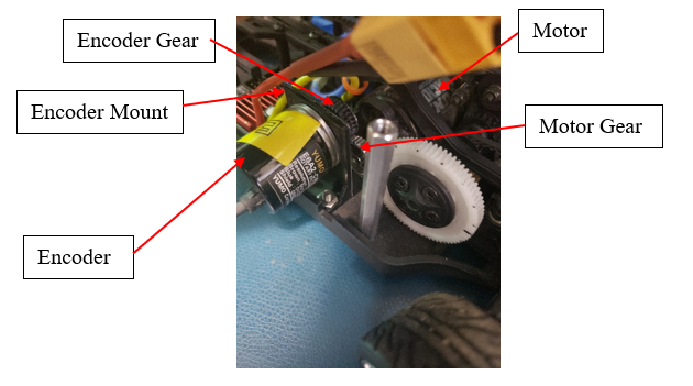
The RC car did not come with an encoder on it and there was no way to access encoder information from neither the ESC nor the DC motor. However, our localization algorithm required odometry information from an encoder to function correctly. To solve this issue, we added an external encoder to the RC car. The encoder we used was a Yumo E6A2 rotary encoder with 200 pulses per revolution. The mount that we designed for the encoder, the parameters for the gear that connected the encoder to the drive train, and the final mounting spot of the encoder are shown below. The gear was designed so that one revolution of the encoder would be equal to one revolution of the motor shaft. Including an encoder also allowed us to better control the speed of the RC car by measuring the current RPM of the motor. More information on this is included on the controls page.
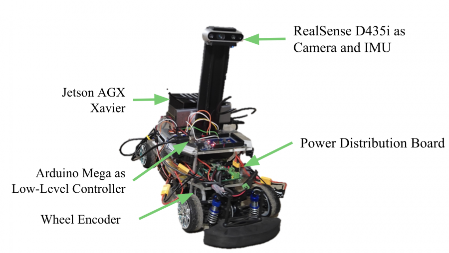
The final elements to be added to the RC car were the Jetson Xavier computer and its power supply. A picture of the final, fully integrated RC car is included below.
Upgrading to Yamaha ATV
Moving on to Fall 2022, we had no access to a drive-by-wire Zamboni vehicle yet, so we decided to scale our autonomy stack onto a Yamaha ATV while waiting for the drive-by-wire retrofitting in parallel.
The ATV comes as drive-by-wire. In particular, it’s steer-by-wire with a large brushed DC motor which drives a ring attached to the steering wheel through a chain & sprocket linkage. It’s throttle-by-wire by a rotary actuator that pulls on a housed wire rope cable. It’s not brake-by-wire.
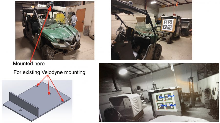
Since all sensors we need for the autonomy are already installed on the ATV except the camera. We mounted our camera as follows:
We then run extensive experiments and unit testing for weeks on ATV to make sure our autonomy stack is robust enough so it can be easily scaled to Zamboni once the retrofit is finished.
Finally! Upgrading to Zamboni
Thanks to ISUZU, we are able to receive the drive-by-wire Zamboni vehicle on time. The vehicle is steer-by-wire with a belt drive to control the steering shaft using DC motor. It’s throttle-by-wire with openCAN-based control for motor throttle. It’s brake-by-wire with an electric-hydraulic pump.
We then mounted the camera on the front of Zamboni. We integrated our code with the ROS nodes for communication between the autonomy and the ECU. We tested the leader-following system that were already validated on ATV but now on Zamboni. We implemented the obstacle detection functionality and tested it on Zamboni as well.