Blender Render: Synthetic Image Generation
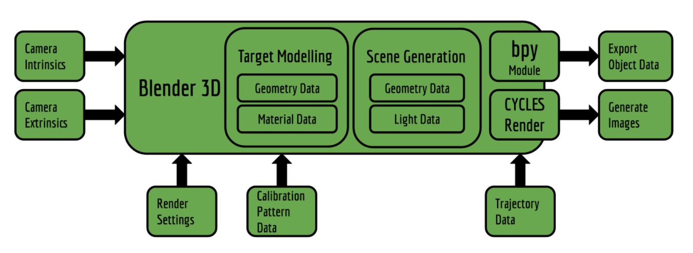
The goal is to design an intermediate system which someone without the prior knowledge of blender can use to generate scenes, objects and images in Blender 3D with minimal inputs and interaction with Blender. Thus, I conceptualized a blender based image generation pipeline which enables a layman to generate images for various camera calibration, validation and testing purposes. The figure below shows the blender pipeline conceptualized and implemented during the spring semester.
System description
It is very important to validate that the geometric calibration algorithm is working as it should, this is where synthetic data comes in. Software engineers need to test their algorithms performance and function during the development process as well as to evaluate results at the time of deployment. Blender 3D provides a good platform to generate great synthetic data for testing the actual functioning of the geometric calibration algorithm. The synthetic data generation pipeline (Figure 7.4.1) loads in camera data (intrinsic & extrinsic), object data (calibration target), required configuration and the number of the cameras and the render settings. It spews out Images and other mesh data using the cycles render engine and bpy (blender-python module) module.
Blender rendering pipeline
Modelling
The modeling of the virtual environment entails many subsequent modeling and programming stages as listed out below.
Calibration Target Mesh Model: Icosahedron
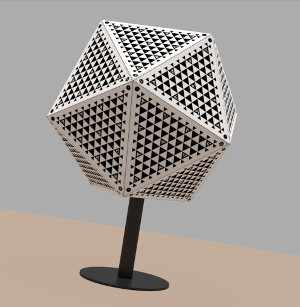
Using the model editor, the mesh model of the Icosahedron was created in Blender 3D. The mesh model of the required dimension has been shown below; This mesh model was then covered with faces created from the vertices of the model. The convergence was parabolic so the model has sharp edges as it would have in the real world and not razor sharp as a computer generated model generally have. The surfaced model is shown below.
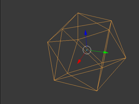
Mesh Model of the Icosahedron
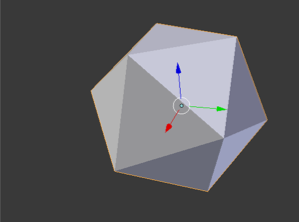
Surfaced Model of the Icosahedron
Calibration Target Mesh Texture: UV Unwrapping
The target pattern has to be imprinted onto the 3D model of the calibration target. This is achieved using a feature known as UV unwrapping in 3D modeling. Here we split the image into an unwrap pattern and this unwrapped pattern is mapped onto the 3D object in the environment. The orientation of the faces on the calibration target is very specific and this has to mapped exactly to the designated vertices of the Icosahedron. The pattern has to digitally mapped with sub-pixel precision. Paper bump map has been applied to the surface of the target.
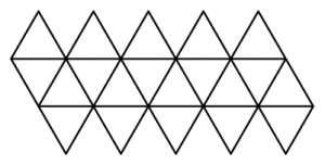
Unwrapping Style.
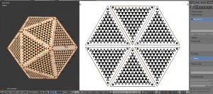
UV Mapping of the pattern layout onto the calibration target.
Visualizing the planes of the patterns
The process of marking the geometric locations of the face patterns involves the assignment of a local reference frame on the calibration target (any one vertex of the target), then assigning each face of the target a local reference frame and finally relating all these frames to the world frame. The reference frame for each individual face is set according to some parameters relating to the geometry of the calibration target itself. The Z axis is aligned along the face normal, the X-Y axes are chosen such that each face’s geometric pattern can be described using just on a single description file. Now in figure one can visualize the reference frames of the faces as well as the calibration target with the script that I have written. This script stores the required data for exporting inside the blender environment and its data blocks, this means that everything is contained inside a very small sized blender file (.blend extension) and can be generated on demand on any computer or terminal.
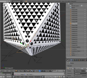
 Mappings on Calibration Target Visualized (with & without target)
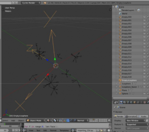
Importing data in Blender (Camera, Trajectory, Object)
The Camera Data and Trajectory Data for the objects are imported into blender using a predefined CSV as visualized.
Camera Visualizations.
Lighting of Environment
The lighting for now has been achieved using a simple “SUN” model whereby the whole environment is bathed in uniform light with no specularity. (specular: the property which dictates the sheen/shine factor of a surface).
Simulation
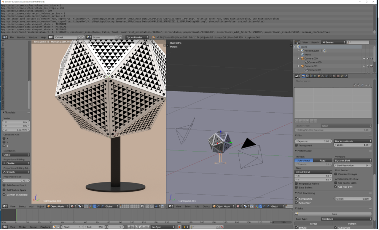
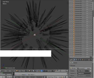
Automated Image Generation
The rendering for all the cameras can be pushed into the render stack by using a click of a button. The output is shown via a diagnostic snippet we wrote to monitor the status of the render pipeline. This diagnostic tool can be activated in the blender environment on MAC/Windows/Linux with ease is compatible with Terminal/Command Promt.
Final Results
The final quality of a sample render is shown below.