
The first step for achieving this goal of motion tracking and 3D reconstruction involves accurate calibration of the sensors. The scope of the project involves calibrating these sensors accurately using a robotic arm and an engineered calibration target.
The basic system setup has been shown below.
The calibration target would be attached to the end effector of the robotic arm, which would move around in the capture system and calibrate the sensors attached to the capture space. The calibration process would involve four methods, namely: geometric calibration of the cameras, estimation of the illumination: light field calibration, photometric calibration of the cameras and acoustic calibration of the microphones.
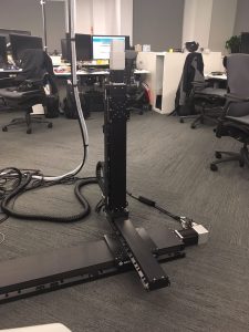
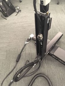
In the first stage we are testing the geometric calibration on a smaller and manageable case by using a 3-axis linearly actuated 3 degree of freedom(DOF) prismatic jointed robot, namely the AEROTECH robot.
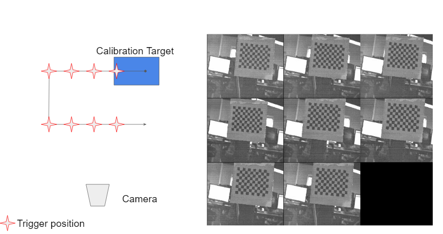
It is of paramount importance that one has the ability to plan and execute the desired trajectory of the calibration target in order to achieve a successful geometric calibration of the camera. The trajectory is embedded with set points at which the camera is triggered by the PSO to capture images of the calibration target. This dictates some amount of motion planning. The AEROTECH programming environment is equipped with command sets which come in handy for trajectory generation.
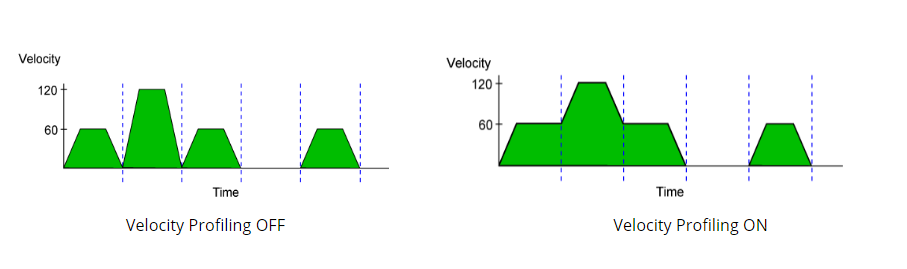
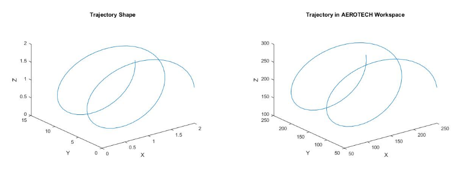
The next step is executing desired motion in 3D space. We decided on going with a Helical path as it gives us a good test bed to perform camera calibration in a wide variety of positions. Also, we have successfully been able to fire the PSO for all 3 axes with multiple window tracking, so that helps us trigger the camera at desired set points even when traversing a 3D path. Some work has been done on velocity profiling, to prevent jerky motions when the robot changes acceleration or velocity or both.
The steps in sequence highlight the stages of system implementation for the AEROTECH robot arm:
- Robot setup : Assembling the robot, wiring it to the controller and mounting it.
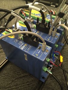
- A3200 controller setup: Daisy chaining the controllers to achieve 3-axis PSO triggering, with X axis controller being the master and Y & Z being the slaves.
- Cable management: Installing cable carriers to avoid cable entanglement.
- XYZ-axes motion : Testing motion of robot along all axes.
- PSU for Z-axis: Power Supply Unit for Z-axis motor as the controller’s inbuilt power supply unit seems to be malfunctioning.
- Continuous pulse output – Testing PSO : Testing the performance of Position Synchronized Output from the robot.
- Multiple axis PSO triggering : Configuring the PSO of the robot to trigger the camera when desired set points are reached.
- Multiple axis PSO triggering, PULSE mode: Integrating the PSO output from the robot with the camera trigger setup ans successfully capturing images.
- Trajectory generation: Helical Path
- Velocity Profiling : To reduce jerks and motion blur while capturing images.