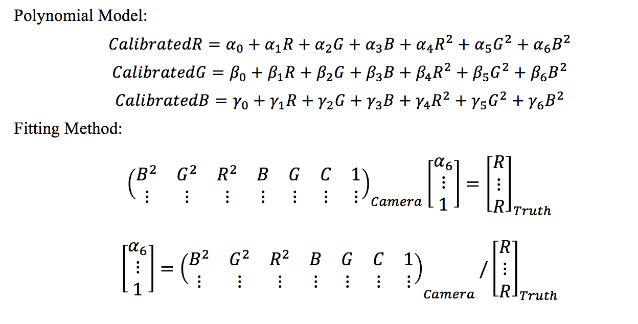
Overview
After our team meeting with Oculus, we set up several tasks for this semester. First, we are continuing the sensor noise calibration. An integrating sphere will be added into our system for high accuracy performance. Second, after proving the RGB photometric responses are linear, we are going to conduct color calibration and generate the mapping function of color sensors. Third, we will keep doing the geometric calibration. Fourth, in addition to the real-world experiment, a simulation is required. We will use Blender to generate simulated images of virtual targets from virtual cameras.
Color Calibration
Color calibration is to measure and adjust the color response of a device (input or output) to a known state. We use an X-Rite ColorChecker Classic Card [Fig. 1] as our ground truths (The manufacture gives us the true color values) and aim at mapping the colors recorded by the cameras these ground truths.
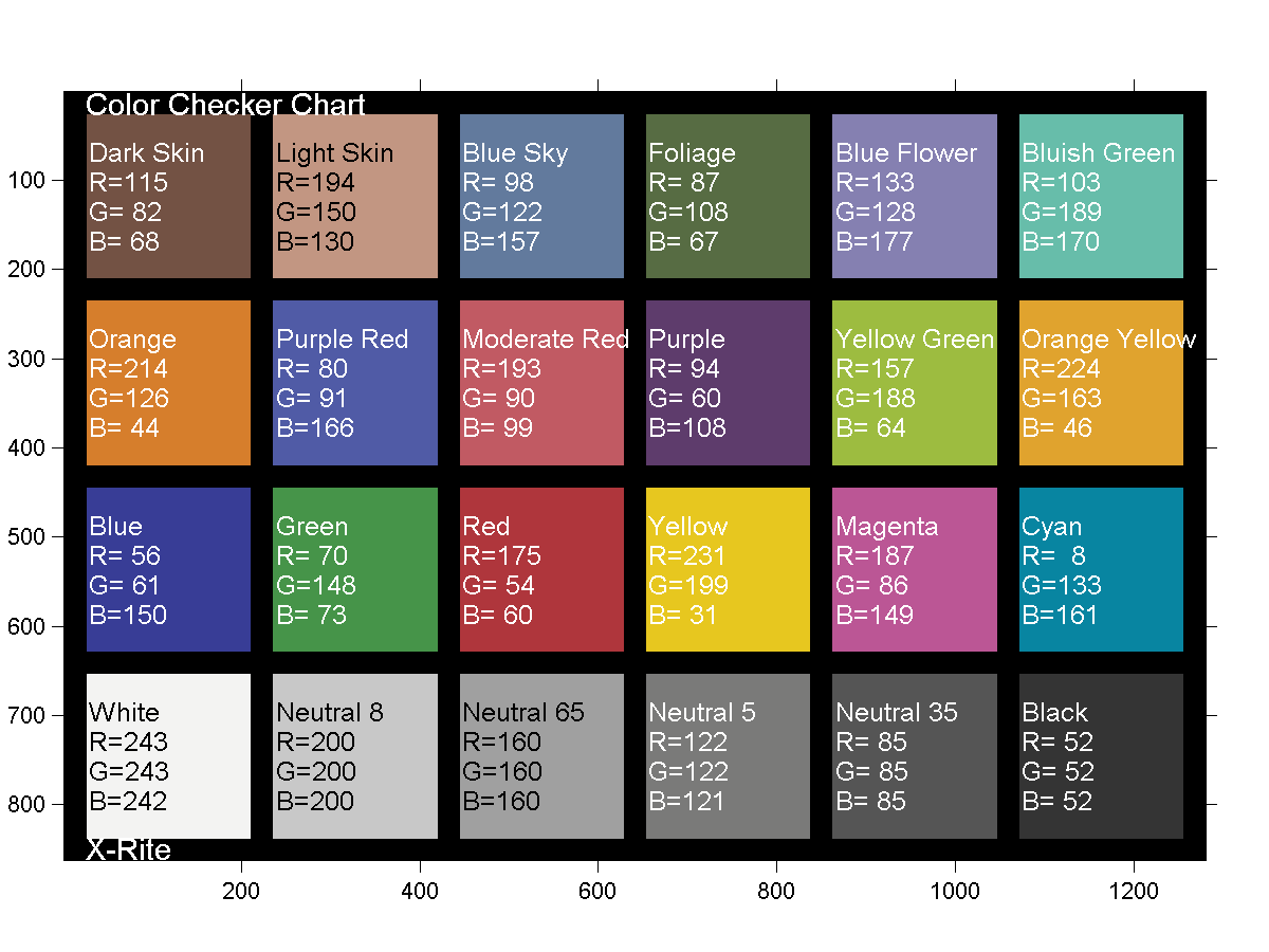
Figure 1. An X-Rite ColorChecker Classic Card
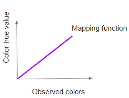
Figure 2. Mapping function (unreal): This graph is only for illustrating the concepts
Color Calibration Pipeline
My first plan was to divide and conquer the problem by doing color patch segmentation first and address the color board detection part later. I wanted to combine these two parts to get the algorithm which can detect each color on the colorchecker in the images.
However, I found this pipeline complicated the problem. Since I have the contour of the color checker which is a very strong information, I should use this information for color checker detection as well as segmentation.
Therefore, I did a lot of researches on how to use colorchecker properties to find it in an image. I found several researchers had similar needs of an automatic colorchecker finder and their developed algorithms. I tried them all and found two of them work well. One of them is Macduff, another is CCFind.
Macduff
Macduff could find and segment the colorchecker successfully. This algorithm is also quite efficient. Nonetheless, when I tested it with complex background, I found that this algorithm cannot work when the colorchecker does not occupy the majority part of the image.
CCFind
In fact, I found this method before Macduff. Yet, when I take the image with the complex background I thought that this method could not address images with complex background. It failed to find out the color patches and when I traced the code I found in succeeded cases, it cut off all background edges cleanly while in failure cases the background edges remained. I thought this prevented it from getting the repeated squares.
After Macduff algorithm failed in robust tests, I studied all the algorithms trying to build my own colorchecker detector. When I once again traced CCFind’s code. I found that it did several downsampling in the code itself, which made me guess the reason it failed before is because of the image size. Therefore, I downsample my images first before applying CCFind on them. The results are good. Furthermore, since CCFind only use the contour information of the colorchecker, it would not be affected by bad lighting conditions.
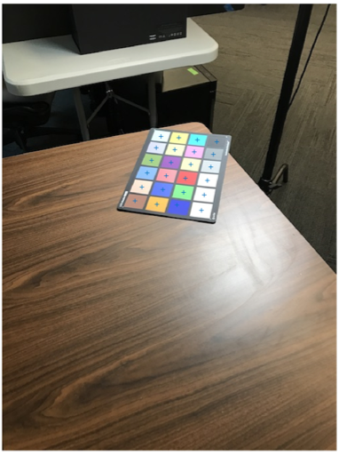
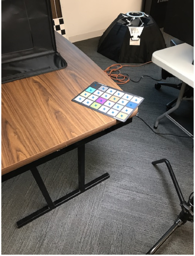
Figure 3. CCFind is robust while
- the colorchecker only occupies a small portion of the images
- images are taken in special light conditions
Mapping Function
Verification
Three verification methods are used here:
Method 1. Error comparison of before and after calibration
Errors mean the difference between the recorded color values with the ground truth values.
<IMG_1462.JPG> (The image was taken in yellow light)
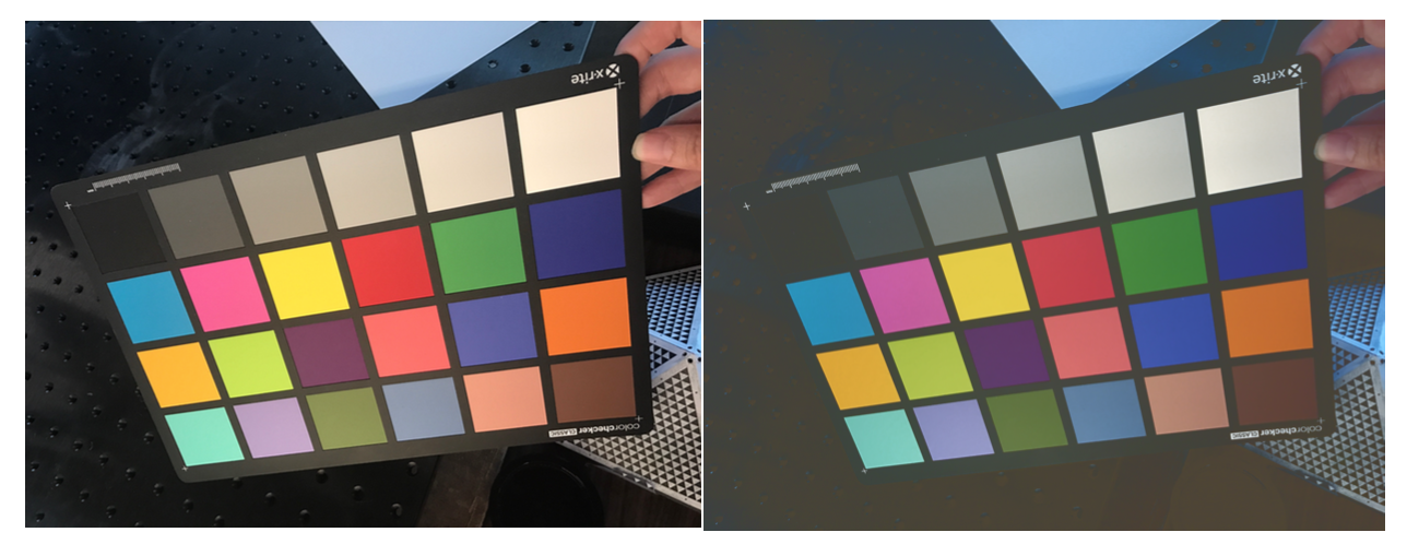
Figure 4. The left image is the input image and the right image is the calibrated image.
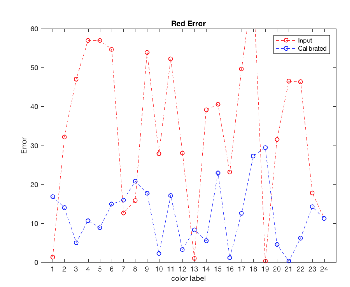
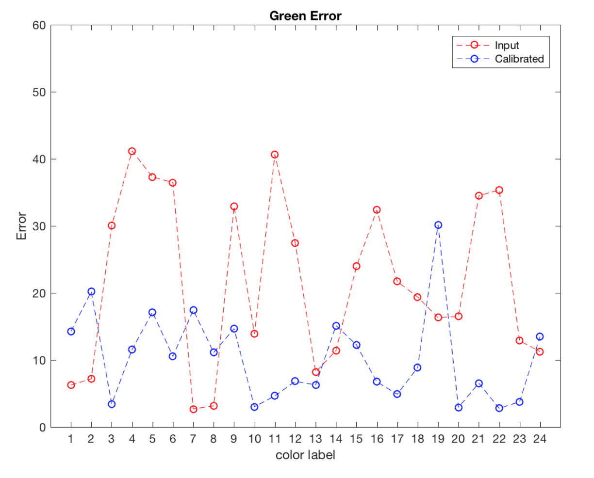
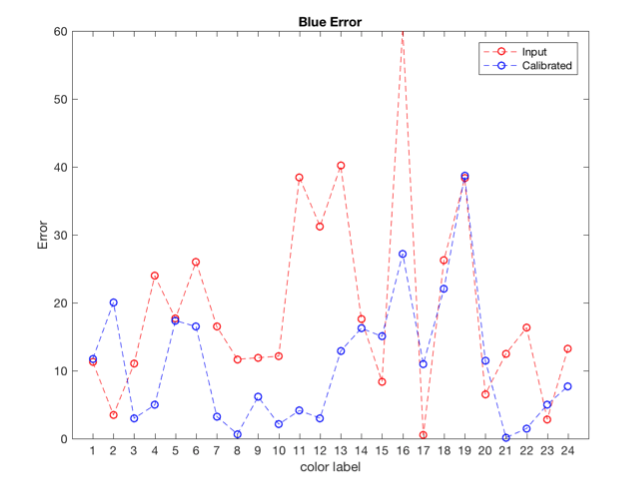
Figure 5. Errors in IMG_1462.JPG and its calibrated result
We can see that in each channel of the input image, the errors reduce generally. However, there are some color patches that become worse after calibration.
Method 2. Error differences between two calibrated images
According to the Xrite standard, when using sRGB ground truth for calibration, the calibrated image should perform like the colorchecker in illuminant D65, which means no matter in what lighting condition the images were taken, they should look similar after the calibration. It can be seen in images below that after the calibration, the color differences become much smaller. The difference means the absolute value of the difference between the according to color patches in IMG_1461 and IMG_1462. In addition, we can see that in Figure 4 and Figure 6 the original images look quite different because of the different lighting condition but after calibration, they look much more alike.
<IMG_1461.JPG> (The image was taken in normal office lighting condition)
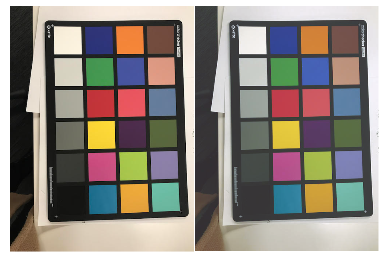
Figure 6. The left image is the input; the right image is the output
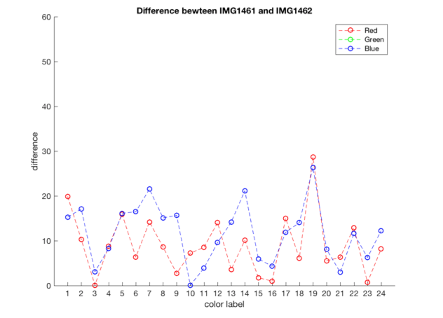
Figure 7. Differences between IMG1461 and IMG1462 after calibration
Method 3. Manipulate the colors and see how it performs after calibration
IMG_1462.JPG Green Channel*1.05 (5%)
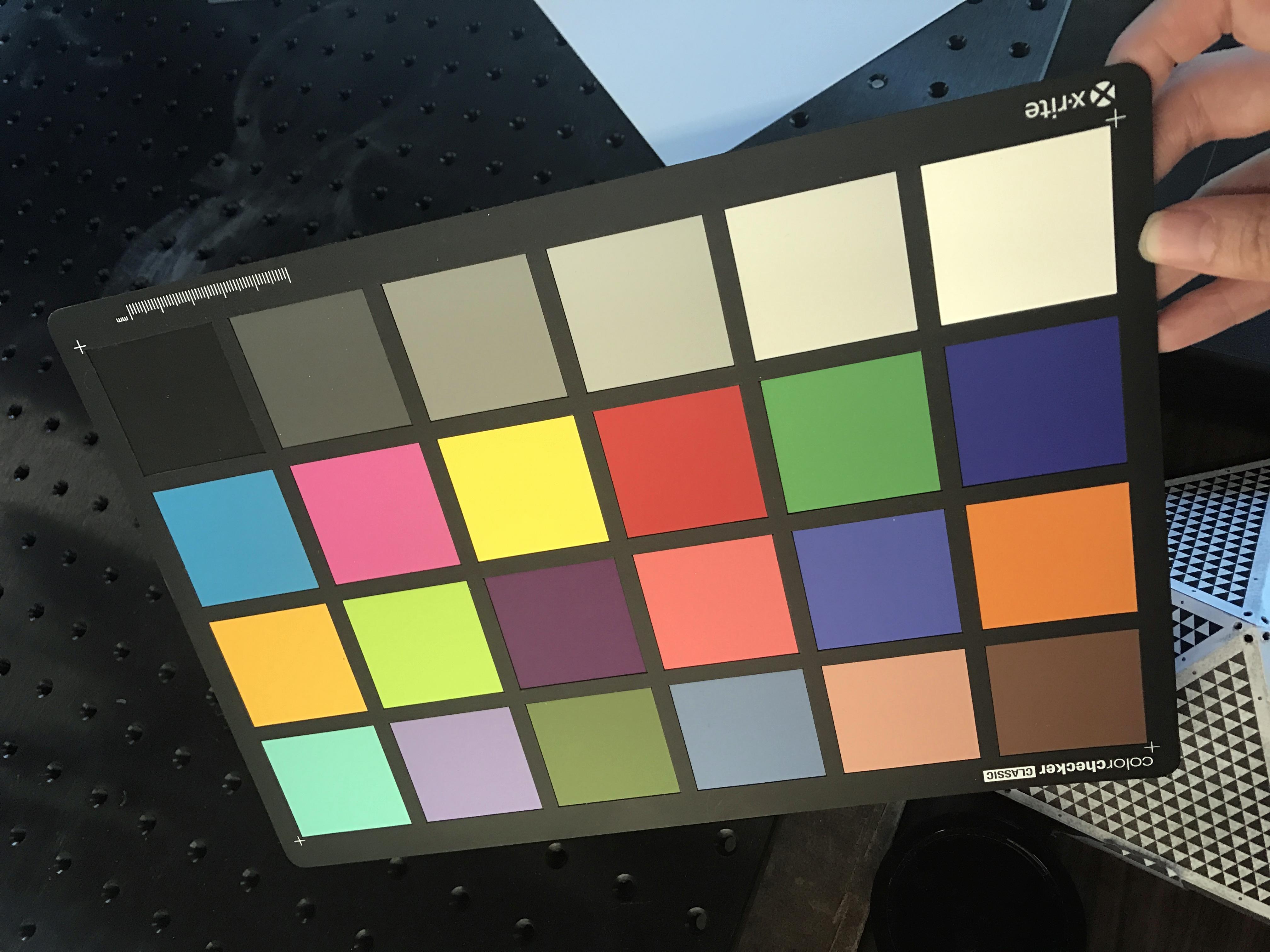
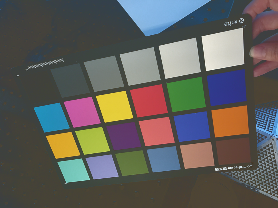
Figure 8. The left image is manipulated image and the right image is the calibrated image
Current Challenge:
After comparison, it is shown that the calibrated results indeed are generally better than before calibration. However, some
color patches have worse performance. This is still worth analyzing. I am guessing it might be the problem of my fitting method.
The matrix is not a square matrix and does not have an inverse matrix. Hence, I am using pseudo-inverse matrix to solve the problem. This can lead to some errors. I will try to use other polynomial fitting method to redo the algorithm
and compare the results.