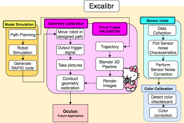
The functional architecture (Figure 4.1) can be divided into the following sub-systems broadly: Robot simulation, Geometry calibration, Virtual Image Generation, Sensor noise calibration and Color calibration.
Generally speaking, when we push the start button, the whole system will begin by checking the safety situation and present accuracy, if the system needs calibration, we will carry out the four steps of calibration procedure successively.
1. Model simulation
In the model simulation, we are working on ABB robot arm model simulation and path optimization.
1.1. Robot model simulation
In the Robot model simulation, we would simulate the working environment of the ABB robot arm and the robot movement. The most important concern here is using simulation system to test the different type of robot movement and make sure all the positions along the robot trajectory are safe and valid. In the simulation, we would check the joint limit of the ABB robot arm and whether there would be collisions. It could save us tons of time to work on the real robot.
1.2. Path Planning
In the Path Planning, we tried to simulate the field of view (FOV) of the hundred of cameras in the environment and based on the requirements of the input to the geometry calibration, the Depth of field where the cameras are able to focus and the working range of the ABB robot arm to optimize the path. Generally speaking, we wanted to generate the path with high coverage of FOV for each camera and reduce the duplicate positions to make the path become more efficient.
2. Geometric calibration subsystem
The task of geometric calibration can be divided into 3 parts: the manipulation and control part, the image capturing part and the data processing and calibration part.
2.1. Virtual Image Generation
This is a virtual image data set generation system to aide in validation of the geometric calibration algorithm for a 3D calibration target. The pipeline loads in camera data (intrinsic & extrinsic), object data (calibration target), required configuration and the number of the cameras and the render settings. It spews out Images and other mesh data using the cycles render engine and bpy module.
2.2. Manipulation and control
From the access terminal, we give instructions to control the ABB Robot Arm which has the 3D calibration target and sensors mounted on it. The ABB robot arm will then move the calibration target in a pre-designed trajectory according to the path design algorithm, and the sensors on it will collect position data. The system will send back the encoded positional data back to the computer and used for the following calibration procedure.
2.3. Image capturing
Also from the access terminal, we give instructions to the triggering mechanism. Under that mechanism, the 12 MP @ 73 fps canon cameras will be triggered to capture images. For the discrete trigger, the ABB robotic arm will move in a discrete pattern with pause to avoid blurring, and the cameras will be triggered to capture images during the pause. Then this will be comparatively slower, but we will be able to get accurate images for the calibration process. When finishing capturing, all the images will be sent back to the computer and used for the following calibration procedure.
2.4. Data processing and calibration
During this part, we will use the captured image data and the position data of the calibration target to do the geometry calibration. We will run the geometry calibration algorithm to do the calibration work for multi cameras, and then the parameters of cameras and the positional and rotational data will be stored in a certain unit.
3. Sensor noise Calibration
In the sensor noise calibration, we would focus on four type of noise: shot noise, read noise, pattern noise, and thermal noise. In order to minimize these four types of noise influence in the camera for better camera calibration, we would design a noise collection and remove process. With that process, we could systematically record the noise parameter for each camera and conducted the calibration to remove them.
4. Color calibration
Color calibration is to measure and adjust the color response of a device (input or output) to a known state. We used an X-Rite ColorChecker Classic Card as our ground truths. We would try to find the fittest model that could best convert the image color to ground truth color.