
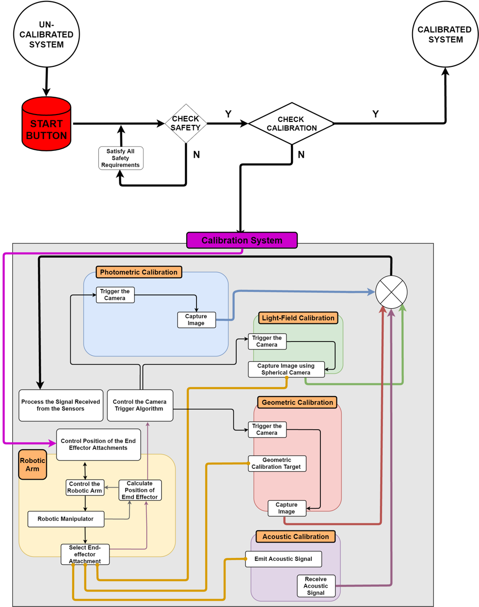
The flow of the functional architecture can be divided into the following components:
- Geometric Calibration: for geometric calibration, a target would be attached to the end effector of the robotic arm. The position of the calibration target would be calculated using the position encoders mounted on the robotic arm and would be sent back to the controller (for feedback control) and the computer/ access terminal. The access terminal would trigger the cameras based on the position of the calibration target. The camera would capture the image of the target and feed it into the calibration algorithm which would then compute the parameters required for camera calibration. The target can be programmed to move in the following ways:
- Discrete: The target would move to a position and stop. Then a pulse would be sent to the computer which would trigger the cameras to simultaneously capture images. After the image capture, the computer would send the signal to the controller to move the robotic arm end effector to the next position.
- Continuous: The target would move continuously, without stopping. As it arrives at a desired position, it would send a pulse to the computer, which would trigger the cameras to capture the images of the target, while the target would be moving. This method is faster than the discrete motion, but may lead to images with motion blur.
- Light Field Calibration: This method would be used to determine the illumination of the desired space. The first step would involve calibration of a spherical camera mounted on the robotic arm and then this spherical camera would be used to calculate the desired illumination.
- Photometric Calibration: This method involves mapping the intensity of light (in lumens) to the corresponding pixel values. This would require images from the geometric calibration and the light field intensity as a function of space in order to calculate the parameters of photometric calibration.
- Acoustic Calibration: This method involves using a speaker to emit a multi frequency variable amplitude sound signal. The microphones situated on the capture space would receive this signal and the two signals (one emitted from the speaker and one received by the microphones) can be compared in order to compute the position of the microphones.