1 THE PIPELINE
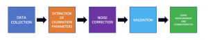
The sensor noise calibration follows the following pipeline:
2 DATA COLLECTION:
2.1 PARAMETERS:
Based on the experiments performed on the EVT HS 12000N camera, the plan is to collect 10 images of both dark and flat images of exposure values ranging from 1000 μs to 30000 μs on intervals of 100 μs from each camera.
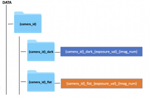
2.2 DATA COLLECTION PLAN:
The images have been named according to a standard naming scheme. The illustration of the directory structure and image naming scheme for the data collection plan can be seen below:
3 EXTRACTING CALIBRATION PARAMETERS
3.1 EXTRACTING THE BIAS MATRIX
- Due to the presence of thermal noise, every image has a bias and a dark frame would consist of non-zero pixel values instead of a uniform image of all non-zero pixel values.
- The thermal noise correction can be performed by subtracting the bias frame from the image.
- As thermal noise is a function of exposure, the bias frames have to be stored for a set of exposure values.
- For each image, the bias matrix corresponding to the exposure closest to the exposure of the image has to be chosen for bias correction.
3.2 EXTRACTING THE GAIN MATRIX
- Due to the presence of pixel response non-uniformity, every pixel of the image has a different capacity of capturing the light from the environment.
- The pixel response non-uniformity correction can be performed by multiplying the gain frame with the bias-corrected image.
- As pixel response non-uniformity is a function of exposure, the gain frames have to be stored for a set of exposure values.
- For each image, the gain matrix corresponding to the exposure closest to the exposure of the image has to be chosen for gain correction.
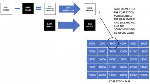
3.3 STORING THE GAIN AND BIAS MATRIX
- The flat and dark images at different exposures are used to compute the gain matrix and bias matrix.
- These correction matrices and their corresponding exposure values are then stored in a file format as shown below:
4 SENSOR NOISE CORRECTION
CORRECTION:
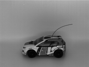
The gain and bias matrices extracted from the correction.mat file is used to correct uncalibrated image. The results are:
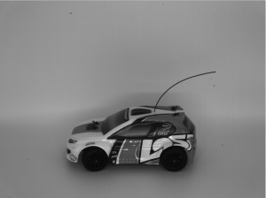
UNCALIBRATED IMAGE:

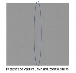
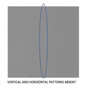
VALIDATION:
A comparison between a uniform patch from the uncalibrated image and a patch at the same location on the calibrated image shows the absence of patterns/stripes, hence validating the image calibration. These results can be seen from below:
5 IMAGE NOISE AND MEASUREMENT
5.1 READ AND SHOT NOISE